
Magnetic-pole detecting system for synchronous AC motor and magnetic-pole detecting method therefor

a synchronous ac motor and magnetic-pole detection technology, applied in the direction of motor/generator/converter stopper, dynamo-electric converter control, instruments, etc., can solve the problem of complex magnetic-pole detection system, and achieve the effect of damping the oscillation of the moving element and shortening the distance that the moving element travels

Inactive Publication Date: 2008-01-29
MITSUBISHI ELECTRIC CORP
View PDF12 Cites 0 Cited by
  • Summary
  • Abstract
  • Description
  • Claims
  • Application Information

AI Technical Summary

Benefits of technology

[0011]The present invention is made to address the foregoing issues and has an object of providing a simplified magnet-pole detecting system and a magnet-pole detecting method therefor that employ an open-loop control system not requiring feedback of the position, the speed, and the like of the moving element, and moreover that shorten the distance that the moving element travels to a stable point, and damp the oscillation of the moving element caused by the control system.

Problems solved by technology

However, in the conventional magnet-pole detecting system, in order to inhibit the oscillation of the moving element, a speed detector for detecting the travel speed of the moving element and a phase compensator for compensating the current phases in correspondence with the travel speed of the moving element must be provided, and furthermore the speed feedback value of the moving element has to be adjusted, and thus there has been a problem in that the magnetic-pole detecting system is complex.

Method used


Image

  • Magnetic-pole detecting system for synchronous AC motor and magnetic-pole detecting method therefor
  • Magnetic-pole detecting system for synchronous AC motor and magnetic-pole detecting method therefor
  • Magnetic-pole detecting system for synchronous AC motor and magnetic-pole detecting method therefor

Examples


embodiment 1

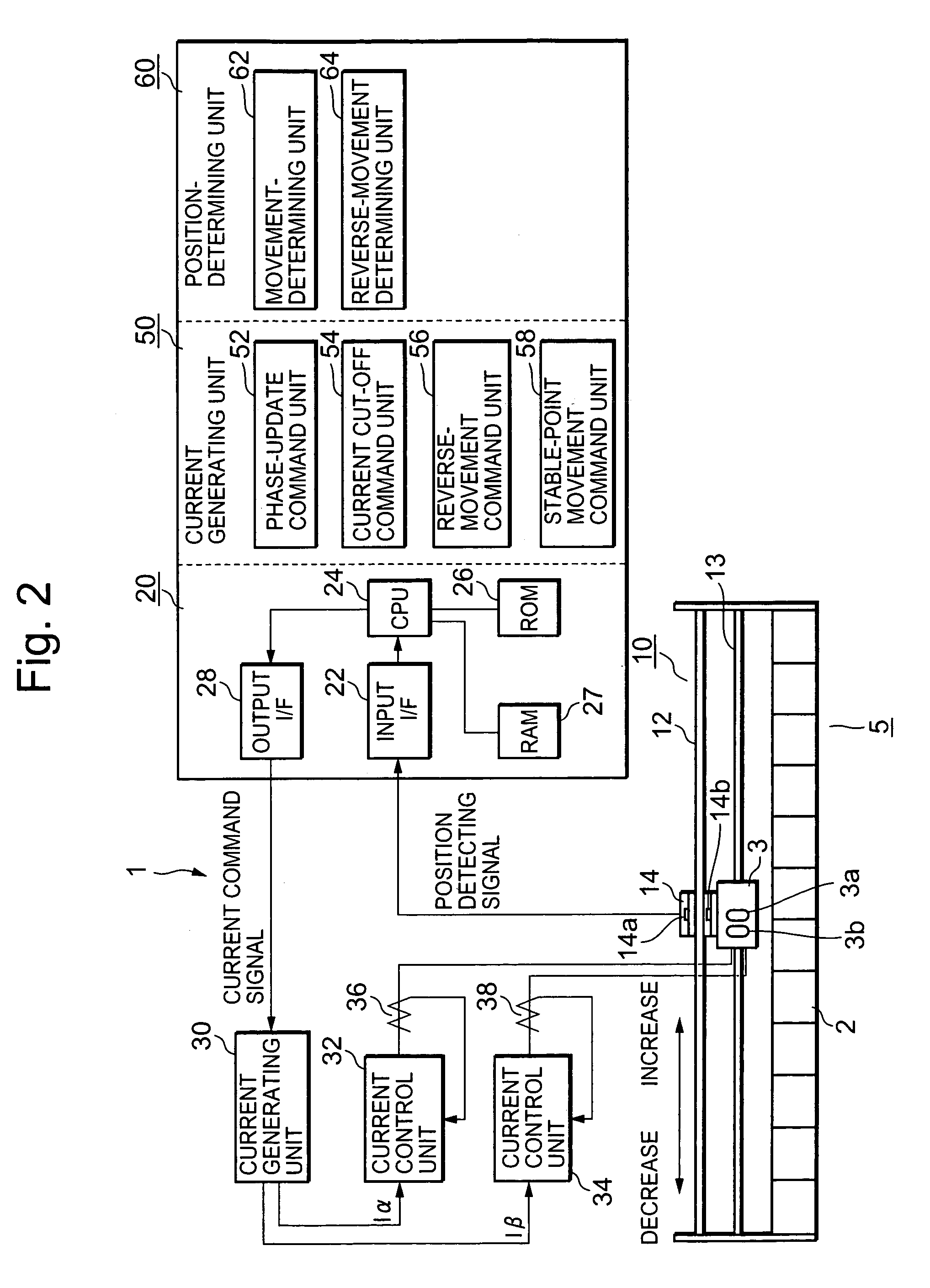
[0065]An embodiment of the present invention that implements the foregoing position-detecting principle for a moving element is set forth referring to FIG. 2. FIG. 2 is an overall block diagram of a magnetic-pole detecting system in a synchronous AC motor.

[0066]In FIG. 2, a magnetic-pole detecting system 1 is equipped with a 2-phase, linear synchronous AC motor 5 (referred to as an AC motor, hereinafter) that has a stator 2 and comprises a moving element 3 with an α-phase coil 3a and a β-phase coil 3b, each phase coil being arranged facing, and having a predetermined gap with, the stator 2; a position detector 10 that detects the position of the moving element 3; a microcomputer 20 that generates an electric current command signal for making currents flow in the AC motor 5 and that executes predetermined processes based on position-detecting signals from the position detector 10; a current generating unit 30 that is connected to the output of microcomputer 20 and, based on the curre...

embodiment 2

[0094]Another embodiment of the present invention will be described, mainly according to FIG. 4. The foregoing embodiment was described ignoring the influence of cogging torque that originates in the AC motor 5; however, in fact, sinusoidal cogging torque Tc occurs as shown in FIG. 4. Therefore, in the present embodiment, a highly accurate magnetic-pole detecting system that is unsusceptible to the cogging torque Tc is set forth.

[0095]It is known that the maximal value of the sinusoidal cogging torque Tc occurs m times over a range of 2Π in terms of electrical angle of the moving element 3, wherein m is the least-common multiple of the number of slots in the stator 2 and double the number of pole-pairs Pt.

[0096]In this situation, for example, if the stator 2 has 12 slots and 8 poles, this least common multiple m is 24; therefore, positive or negative peak values of the cogging torque Tc occur every 15 degrees, and the cogging torque Tc becomes zero every 7.5 degrees as given by elec...

embodiment 3

[0099]Embodiments 1 and 2 above described the detection of positions of the moving element 3, ignoring the influence of friction. However, in reality, since friction exists when the moving element 3 moves, the stable point of the moving element 3 differs from its standstill position. In order to reduce the influence of this type of friction, a means is available for increasing the currents flowing in the coils 3a and 3b of the moving element 3 so that the attractive force of the moving element 3 is increased, but such a means is not appropriate since, when the currents flowing are increased, the rated current of semiconductor devices forming the current generating unit 30 increases.

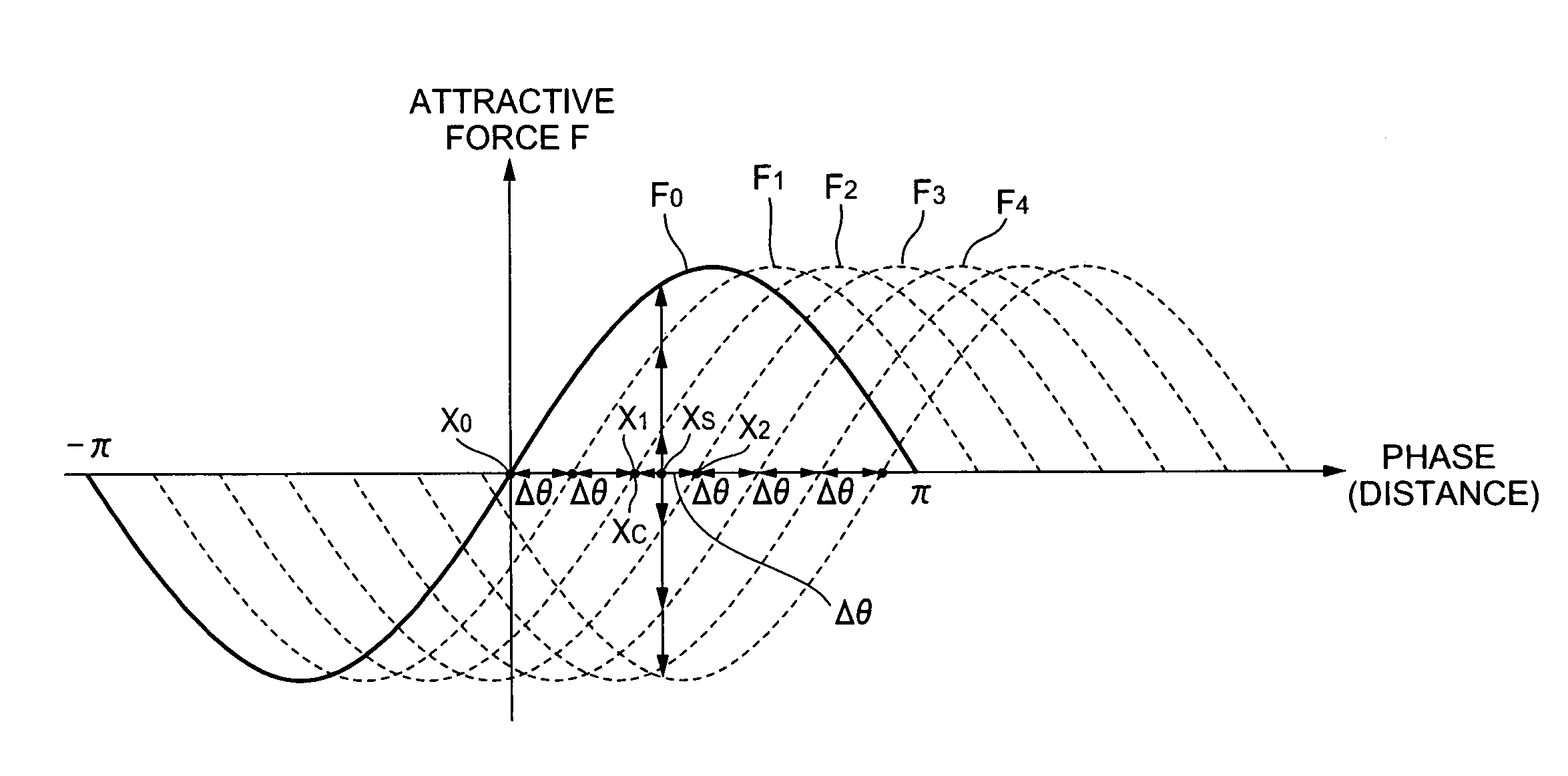
[0100]Therefore, a magnetic-pole detecting system is set forth according to FIG. 5, wherein the accuracy of detecting the magnetic-pole positions of the moving element 3 is raised without increasing the currents that flow in the coils 3a and 3b. FIG. 5 is a characteristic curve chart representing the attr...


PUM


Abstract

A magnetic-pole detecting system for synchronous AC motors and a magnetic-pole detecting method therefor are provided. The magnetic-pole detecting system for synchronous AC motors includes a position detector 10 for detecting the relative position between the moving element 3 and the stator of an AC motor 5; a phase-update command unit 52 for making a plurality of currents with different phases flow in coils 3a and 3b so that the moving element 3 moves to a plurality of stable points; a reversal command unit 56 for making currents flow in the coils 3a and 3b so that the moving element 3 reverses from the previous direction in which the moving element 3 has been moved by the phase-update command unit 52; a current cut-off command unit 54 for cutting off the currents flowing in the coils 3a and 3b when the position-detector 10 detects a movement of the moving element 3; a reversal-determining unit 64 for determining, based on a position-detecting signal from the position-detector 10, a direction in which the moving element has moved based on the phase-update command unit 52, and for determining that the determined direction has reversed between the previous and the present instances; and a stable-point-simulator for simulating a stable point by means of the phase of the currents flowing in the moving element 3 when the reversal-determining unit 64 has detected the reversal.

Description

TECHNICAL FIELD[0001]This invention relates to magnetic-pole detecting systems for synchronous AC motors (referred to as a magnetic-pole detecting system, hereinafter) and magnetic-pole detecting methods therefor, and more particularly, to improvement in initial magnetic-pole detection.BACKGROUND ART[0002]In a synchronous AC motor, magnetic-pole position needs to be detected in order to determine the phase of the current that flows in each phase coil. For this purpose, magnetic-pole detecting systems in which magnetic-pole position is detected by making each phase current flow in a certain pattern so that the moving element moves to a corresponding stable point are known.[0003]A conventional magnetic-pole detecting system as mentioned above will be described referring to Japanese Laid-Open Patent Publication 1991-89886. According to the patent publication, a magnetic-pole detecting system detects initial magnetic-pole position by changing the phases of an α-phase current Iα and a β-...

Claims


Application Information

Patent Timeline
Patent Type & Authority Patents(United States)
IPC IPC(8): H02P7/00H02P6/22H02P25/06
CPCH02P6/22
Inventor TAKAHASHI, KAZUTAKAHARADA, YASUNOBU
Owner MITSUBISHI ELECTRIC CORP
Learn More