Rotating electrical machine

a technology of rotating electrical machines and rotating shafts, which is applied in the direction of transmission systems, vehicle maintenance, ac motor stoppers, etc., can solve the problems of limiting the machine lifespan to 2000 hours, causing electromagnetic interference, and causing the spark generated by brushes and commutators

Inactive Publication Date: 2008-01-29
DOLPHIN ELECTRIC HLDG
View PDF28 Cites 2 Cited by
  • Summary
  • Abstract
  • Description
  • Claims
  • Application Information

AI Technical Summary

Benefits of technology

[0043]A rotating electrical machine according to the invention has the advantage of extremely low manufacturing and maintenance costs as the machine requires neither drive electronics nor a brush and commutator set.

Problems solved by technology

The disadvantage of the first type is that electromechanical wear of the brushes and commutator limits the lifespan of the machine to 2000 hours.
Also, as only one coil at a time is energised, there are limits placed on the efficiency of the machine.
Furthermore, the sparks generated by the brushes and commutator create electromagnetic interference.
The second type overcomes the problems mentioned above, but the use of drive electronics makes the machine much more costly to manufacture than the first type.

Method used


Image

  • Rotating electrical machine
  • Rotating electrical machine
  • Rotating electrical machine

Examples


Embodiment Construction

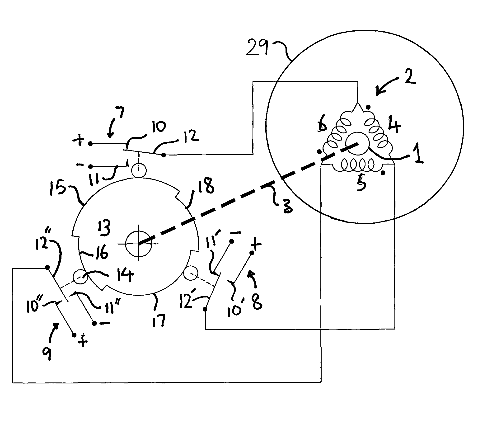
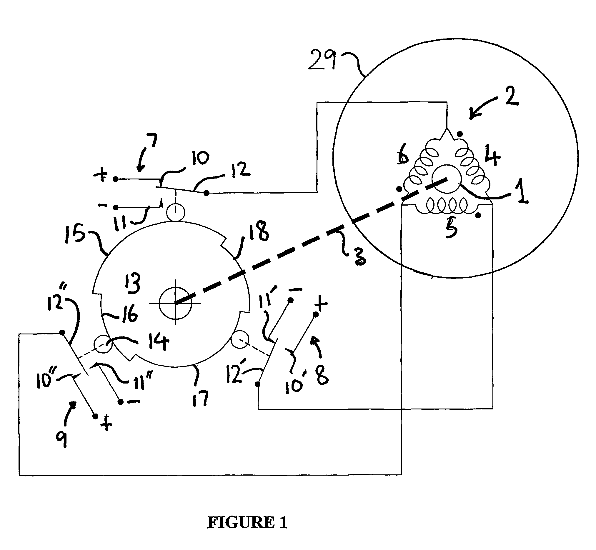
[0032]FIG. 1 illustrates a two-pole rotating electrical machine according to the invention. The machine comprises a housing 29 enclosing a rotor 1 and a field winding 2. The rotor 1 is mounted on a shaft 3 for rotation within the housing, and includes a permanent magnet for establishing a rotor magnetic field. The field winding 2 is positioned about the rotor 1 and includes three delta connected coils 4, 5, 6. This configuration of rotor 1 and field winding 2 is well known in the art and need not be described in further detail.

[0033]In the motor configuration electric current is supplied to the field coils 4, 5, 6 by three single-pole changeover switches 7, 8, 9 operating in sequence. The first fixed contact 10 of each changeover switch 7, 8, 9 is connected to a positive (+) side of a DC supply (not shown) and the second fixed contact 11 is connected to a negative (−) side of the DC supply. The moving switch contact 12 is connected to the field winding 2 to make a positive (+) or ne...


PUM


Abstract

A rotating electrical machine has a housing with a shaft mounted rotatably in it. A rotor is fixed to the shaft and has a plurality of magnetic poles. A stator is positioned about the rotor and has a winding. A switch is mounted within the housing and has a first position for allowing current in one direction through the winding and a second position for allowing current in an opposite direction through the winding. A mechanical activator is movable with or by the shaft and acts on the switch to move it between the first and second positions.

Description

FIELD OF THE INVENTION[0001]The present invention relates to rotating electrical machines, that is machines which can be used either as electric motors, in which electrical energy is converted into movement, or as electric generators in which movement is converted into electrical power.[0002]There are two known types of DC electric motors. In the first type, a DC electrical power source is connected to coils wound on a rotor by means of contact brushes and a commutator. The rotor rotates about, or within, a stator in the form of one or more permanent magnets or separately energised electromagnets. The commutator serves to switch is electrical current between the coils. In the second type, the rotor comprises a plurality of permanent magnets, and the stator comprises a number of wound coils Associated electrical circuitry controls the switching of electrical current between the stator coils.[0003]The disadvantage of the first type is that electromechanical wear of the brushes and com...

Claims


Application Information

Patent Timeline
Patent Type & Authority Patents(United States)
IPC IPC(8): B60S1/08G08C19/16G08C19/28H02K25/00H02P6/00H02P6/14
CPCH02K25/00Y10T74/19647
Inventor MULDOWNEY-COLSTON, TONY ELIJAHSHAW, THOMAS MAHON
Owner DOLPHIN ELECTRIC HLDG
Why Eureka
Try Eureka