Hole-bottom tubular linear motor electric impactor

A technology of linear motors and impactors, applied in the direction of electromechanical devices, electric components, percussion drilling, etc., can solve the problems of hydraulic impactors affecting the working performance, unsatisfactory, and affecting drilling efficiency, etc., to achieve flexible structural size design, The effect of low maintenance cost and simple and strong structure

Inactive Publication Date: 2014-09-03
CHINA UNIV OF GEOSCIENCES (WUHAN)
View PDF2 Cites 7 Cited by
  • Summary
  • Abstract
  • Description
  • Claims
  • Application Information

AI Technical Summary

Problems solved by technology

[0003] 1) Working parameters cannot be adjusted downhole, remote control is difficult, and cannot adapt to the development trend of drilling equipment automation
It is difficult to adjust the impact stroke frequency of traditional hydraulic or pneumatic impactors. Usually, after going downhole, the impact can only be started according to the pre-adjusted impact energy and impact frequency, and it is impossible to make appropriate adjustments to the impact parameters according to different formations.
As soon as the surface mud pump or air compressor starts to run, the impactor is in working condition, and it cannot be controlled by the surface after it starts working underground; when it is necessary to stop working in an emergency, the mud pump or air compressor must be turned off, which may cause burnout. drilling and other accidents
It is impossible to make accurate analysis and identification of possible situations such as air strikes, blocked waterways, and stuck impactors, and can only be judged subjectively by the staff on the surface based on experience
It can no longer meet the needs of today's drilling equipment for a higher degree of automation
[0004] 2) High-power auxiliary facilities are required, with low efficiency and high energy consumption
[0005] 3) Unable to meet some special drilling conditions
However, when performing deep hole and ultra-deep hole operations, when the fluid medium carrying energy required by the hydraulic impactor passes through a long drill string, a relatively large pressure loss (leakage) will occur. This phenomenon occurs in ultra-deep hole drilling. especially evident in the process
In addition, the back pressure of the upward fluid during vertical hole drilling will also affect the performance of the hydraulic impactor, and in severe cases, the impactor will not work
In addition, there are problems such as leakage of the inner cylinder measuring channel and short working life of the jet element, because the average life of the jet element is 60-100h, which seriously affects the drilling efficiency

Method used


Image

  • Hole-bottom tubular linear motor electric impactor
  • Hole-bottom tubular linear motor electric impactor
  • Hole-bottom tubular linear motor electric impactor

Examples


Embodiment 1

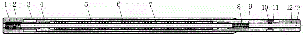
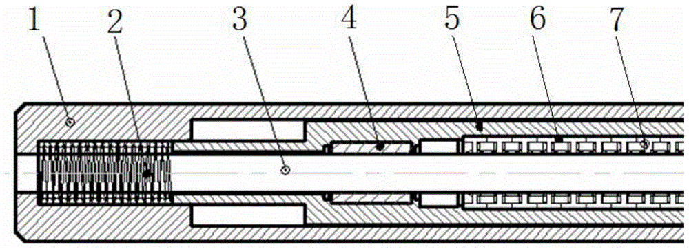
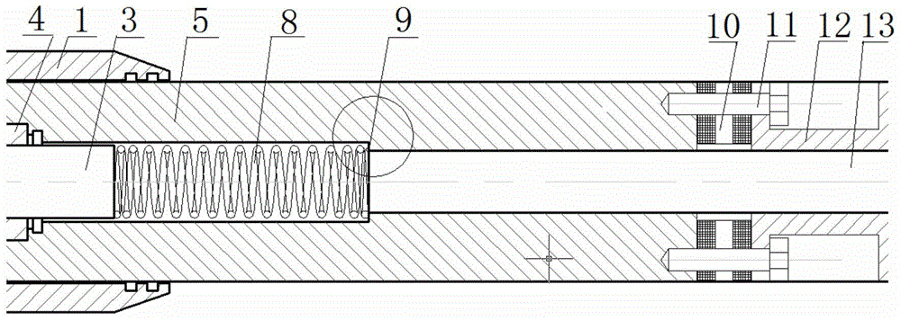
[0027] Embodiment 1: A kind of hole bottom tubular linear motor electric impactor provided by the present invention, its structure is as follows figure 1 , 2 , 3, including motor outer cylinder 1, permanent magnet rod 3, linear ball bearing 4, mover outer ring 5, mover silicon steel sheet 6, mover coil 7, damping spring, buffer gasket 11 and base 12, The motor outer cylinder 1 is the shell of the entire electric impactor, the motor outer cylinder 1 is used to connect with the drilling tool, the permanent magnet rod 3 of the linear motor is fixed on the motor outer cylinder 1, and the permanent magnet rod 3 is used as a straight line The stator of the motor, the permanent magnet rod 3 is a permanent magnet, and the outer ring of the permanent magnet is wrapped with a stainless steel layer. The center of the permanent magnet rod 3 has a chip removal channel 13 for chip removal, and the chip removal channel 13 runs through the entire motor. impactor; the mover outer ring 5 is th...

Embodiment 2

[0030] Embodiment 2: A hole-bottom tube-type linear motor electric impactor provided by the present invention, its structure is basically the same as that of Embodiment 1. The cylindrical linear motor adopted by the invention is suitable for the inner hole space of the drill pipe, the length of the mover and the stator is not limited by the space, and the power of the impactor can be flexibly designed, so that it has the characteristics of large electromagnetic force.

[0031] The main dimensions and electromagnetic parameters of the tubular linear motor electric impactor of the present invention are shown in the following table: some symbols in the table refer to Figure 5 .

[0032]

[0033] It can be seen from the above table: the impactor is calculated according to the impact stroke of 30mm and the mass of the mover of 10kg, and the cylindrical permanent magnet motor with an outer diameter of 62mm is the impactor. The single stroke time is t≈0.1s, α≈3~9g, v≈3~9m / s, th...


PUM


Abstract

The invention relates to a hole-bottom tubular linear motor electric impactor which comprises a motor outer cylinder, a permanent magnet rod, a linear ball bearing, a rotor, rotor silicon steel sheets and a rotor coil. The motor outer cylinder is an outer shell of a linear motor. The permanent magnet rod is fixed to the motor outer cylinder and serves as a stator of the linear motor. The rotor moves relative to the permanent magnet rod through the linear ball bearing. An iron core composed of the rotor silicon steel sheets is inlaid inside the rotor. A groove is formed in the iron core and internally provided with the rotor coil. A three-phase alternating current winding is adopted for the coil, and the three-phase symmetrical alternating current is led into the coil to generate a traveling wave magnetic field coincident with the rotor in the movement direction. Two damping springs are further arranged to be used for buffering shock. According to the hole-bottom tubular linear motor electric impactor, a movable-coil type structure is adopted, namely, the permanent magnet rod and the iron core are fixed, and the coil is movable. Meanwhile, a buffering gasket is designed between the rotor and a base, and the fatigue resistant service life of the hole-bottom tubular linear motor electric impactor is prolonged. The hole-bottom tubular linear motor electric impactor is simple and firm in structure and low in manufacturing and maintenance cost, the impacting stroke speed and the impacting stroke frequency are easy to adjust, and the hole-bottom tubular linear motor electric impactor is high in efficiency and can be used for deep hole drilling.

Description

technical field [0001] The invention relates to a motor design technology, in particular to a tube-type linear motor electric impactor at the bottom of a hole. The impactor of the invention can be widely used in geological equipment, geology, oil drilling engineering, and drilling engineering, and can replace Existing hydraulic impactor and pneumatic impactor. Background technique [0002] At present, there are two types of impactors commonly used in geological and oil drilling engineering: hydraulic impactors and pneumatic impactors. These two types of impactors have the following problems in use: [0003] 1) Working parameters cannot be adjusted downhole, remote control is difficult, and it cannot adapt to the development trend of drilling equipment automation. It is difficult to adjust the impact stroke frequency of traditional hydraulic or pneumatic impactors. Usually, after going downhole, the impact can only be started according to the pre-adjusted impact energy and i...

Claims


Application Information

Patent Timeline
Patent Type & Authority Applications(China)
IPC IPC(8): H02K33/18H02K7/14E21B1/22
Inventor 吴涛姚爱国李勇波何王勇杨代华
Owner CHINA UNIV OF GEOSCIENCES (WUHAN)
Why Eureka
Try Eureka