Reliable method for erasing a flash memory

a flash memory and reliable technology, applied in the field of flash memory erasing methods, can solve the problems of deep over-erase, ersv has to start all, deep over-erase, etc., and achieve the effect of preventing deep over-erase and high efficiency of this method

Active Publication Date: 2008-01-29
ELITE SEMICON MEMORY TECH INC
View PDF3 Cites 1 Cited by
  • Summary
  • Abstract
  • Description
  • Claims
  • Application Information

AI Technical Summary

Benefits of technology

[0009]Accordingly, the present invention is related to a method for erasing one or more flash memory sector(s). The method is capable of erasing non-uniform sectors, sectors which become leaky after being erased and fail in an erase verification, and preventing deep over-erase. This method is faster than conventional methods. The primary cause of the higher efficiency of this method is that there is no need for erase verification every time after an erase operation. The secondary cause is that the conservative erase proposed by the present invention includes the steps of slow program (SLPGM) and slow program verification (SLPGMV) to repair leaky bit lines, and the steps of SLPGM and SLPGMV are executed much less frequently than their counterparts are executed in conventional methods.
[0010]The present invention is also related to a method for erasing a flash memory group. This method prevents deep over-erase, is faster than conventional methods, and saves layout area because only one address counter is used. This method is useful for both group erase and sector erase. This method also saves the time of soft program after erase because only a part of the sectors need to be considered at the soft program stage. In addition, this method classifies flash memory sectors into many types for different procedures.

Problems solved by technology

If such a memory cell is erased again, deep over-erase may happen.
The problem is that whenever a memory cell fails in the ERSV, another erase pulse is applied to the entire group and then the ERSV has to start all over again.
Consequently, the memory cells at the high end of address may be erased an undesirably large number of times and deep over-erase may occur.
However, due to the extra address counters, the flash memory chip in FIG. 3 occupies much more layout space than the chip in FIG. 2 does.
However, it is possible that a sector gets leaky every time and has to be fixed again and again.
A lot of time would be wasted in such a situation.

Method used


Image

  • Reliable method for erasing a flash memory
  • Reliable method for erasing a flash memory
  • Reliable method for erasing a flash memory

Examples


Embodiment Construction

[0029]Reference will now be made in detail to the present preferred embodiments of the invention, examples of which are illustrated in the accompanying drawings. Wherever possible, the same reference numbers are used in the drawings and the description to refer to the same or like parts.

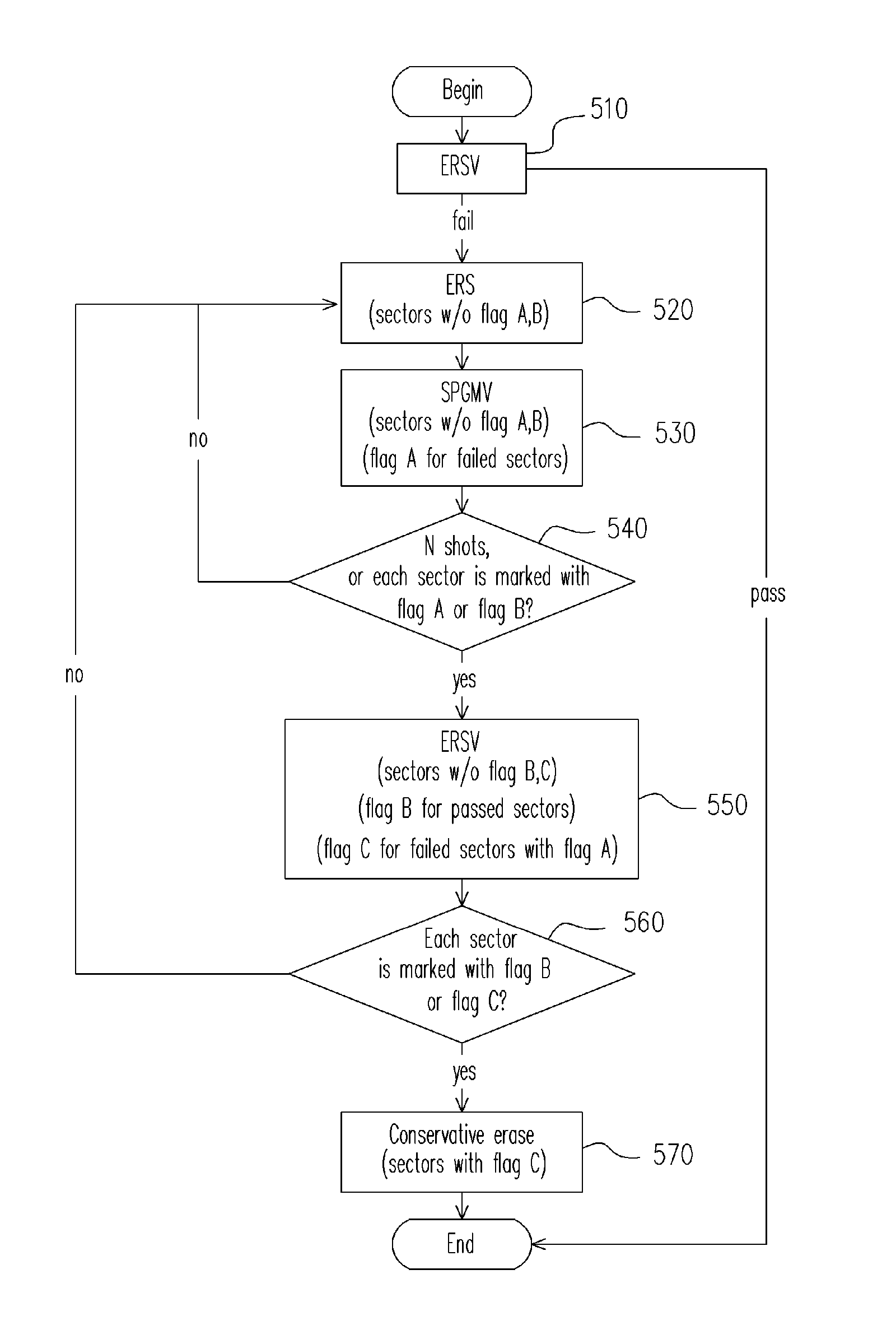
[0030]As is discussed below, the preferred embodiments of the present invention use flags to mark sectors with bit line leakage and sectors which pass the erase verification. Therefore the embodiments below can prevent deep over-erase and improve efficiency by withholding redundant, and sometimes harmful, erase pulses. Another factor contributing to efficiency is that the embodiments below use soft program verification, which is much faster than erase verification, to reduce the usage of time-consuming erase verification.

[0031]FIG. 5 is a flow chart of a method for erasing a flash memory group according to an embodiment of the present invention. The flow begins at step 510. First, an erase verificati...


PUM


Abstract

A method for erasing a flash memory group is provided, which comprises the following steps. (a) Apply a erase (ERS) pulse to a first subset of the group. (b) Perform one of a soft program verification (SPGMV) and a tight soft program verification (TSPGMV) on the first subset of the group. (c) Repeat steps (a) and (b) until a first predetermined condition is true. (d) Perform an erase verification (ERSV) on a second subset of the group. (e) Repeat steps (a) to (d) until a second predetermined condition is true. And (f) fix bit line leakage in a third subset of the group with a slow program (SLPGM) and apply an ERS pulse to the third subset.

Description

BACKGROUND OF THE INVENTION[0001]1. Field of the Invention[0002]The present invention relates to methods for erasing flash memory. More particularly, the present invention relates to a method for erasing non-uniform flash memory sectors and a method for erasing flash memory sector groups.[0003]2. Description of the Related Art[0004]Every time a flash memory cell is erased, there is always a possibility that its threshold voltage becomes lower. Over-erase is the situation when there is bit line leakage in a flash memory cell. If such a memory cell is erased again, deep over-erase may happen. Deep over-erase is unrecoverable and should be avoided.[0005]FIG. 1 is a flow chart of a conventional method for erasing a flash memory sector group. A sector group is a set consisting of multiple memory sectors. An erase (ERS) pulse is applied to a sector group in step 110, erasing all sectors in the group at the same time. And then an erase verification (ERSV) is performed on the group in step ...

Claims


Application Information

Patent Timeline
Patent Type & Authority Patents(United States)
IPC IPC(8): G11C16/04
CPCG11C16/16G11C16/3404G11C16/3409G11C16/344G11C16/3445
Inventor LIN, YANG-CHIEH
Owner ELITE SEMICON MEMORY TECH INC
Why Eureka
Try Eureka