Supercharge Your Innovation With Domain-Expert AI Agents!

Optical disc device

a technology of optical discs and optical discs, applied in the direction of digital signal error detection/correction, instruments, recording signal processing, etc., can solve the problems of increasing power consumption, affecting tracking performance, and providing vibration to the lens actuator, so as to reduce power consumption, eliminate unnecessary driving of stepping motors, and stabilize tracking control

Inactive Publication Date: 2008-01-29
FUJITSU LTD +1
View PDF9 Cites 3 Cited by
  • Summary
  • Abstract
  • Description
  • Claims
  • Application Information

AI Technical Summary

Benefits of technology

The present invention is an optical disc device that includes a lens-position detecting section for detecting a lens position signal, which indicates the position of an object lens with respect to a carriage. The invention removes an eccentric component from the lens position signal to stabilize tracking control and reduce power consumption. The device also includes a displacement detecting section to determine whether or not the carriage should be driven and provide an instruction to begin driving the carriage. The technical effect of the invention is to improve the accuracy and efficiency of the optical disc device.

Problems solved by technology

While such driving of the stepping motor to reciprocate the carriage is an operation needed for accurate tracking, it increases power consumption since it is made inevitably every turn of the disc.
Further, since such driving of the stepping motor is made for a short period of several microseconds, it provides vibrations to the lens actuator, and affects tracking performance.
In the case where the object lens is urged by the spring, during driving of the lens actuator, the returning reaction of the spring generates disturbance in tracking, and possibly decreases the stability in tracking servo.

Method used


Image

  • Optical disc device
  • Optical disc device
  • Optical disc device

Examples


Embodiment Construction

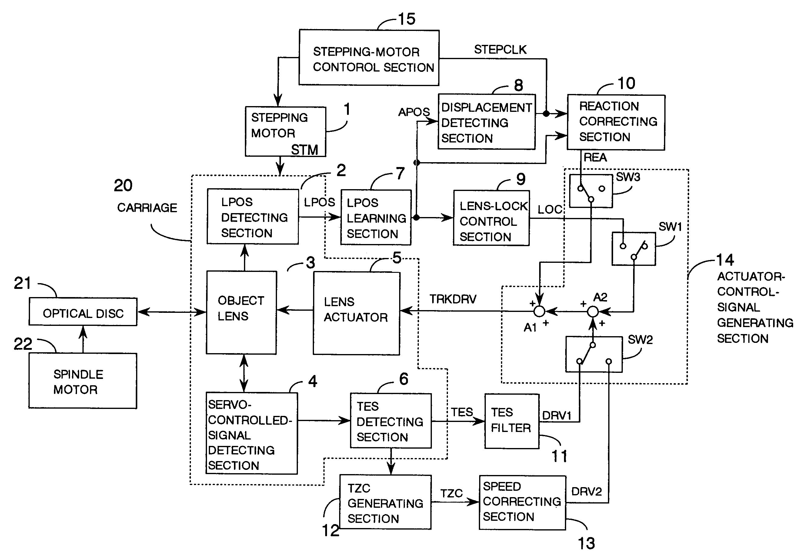
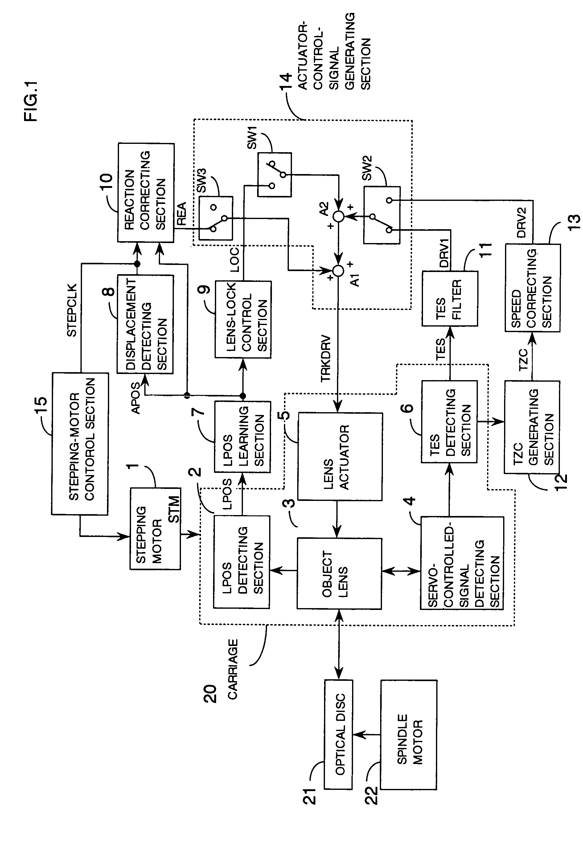
[0039]The present invention provides an optical disc device comprising: a carriage opposed to an optical disc medium and capable of moving in a radial direction of the optical disc medium; a first driving section for driving the carriage; an object lens mounted in the carriage for focusing laser light on the optical disc medium; a second driving section mounted in the carriage for displacing the object lens in the radial direction of the object lens; a lens-position detecting section fixed to the carriage for detecting positional information on the object lens; an eccentricity removing section for generating a position detecting signal by removing an eccentric component of the optical disc medium from the positional information on the object lens; and a displacement detecting section for determining, using the position detecting signal, whether or not the carriage should be driven and for providing an instruction to begin driving the carriage, to the first driving section, based on ...


PUM

PropertyMeasurementUnit
diameteraaaaaaaaaa
distanceaaaaaaaaaa
timeaaaaaaaaaa

Abstract

An optical disc device of the present invention has a carriage opposed to an optical disc medium and capable of moving in a radial direction of the optical disc medium; a first driving section for driving the carriage; an object lens mounted in the carriage for focusing laser light on the optical disc medium; a second driving section mounted in the carriage for displacing the object lens in the radial direction of the object lens; a lens-position detecting section fixed to the carriage for detecting positional information on the object lens; an eccentricity removing section for generating a position detecting signal by removing an eccentric component of the optical disc medium from the positional information on the object lens; and a displacement detecting section for determining, using the position detecting signal, whether or not the carriage should be driven and for providing an instruction to begin driving the carriage, to the first driving section, based on a result of the determination.

Description

CROSS-REFERENCE TO RELATED APPLICATION[0001]This application is related to Japanese application No. 2004-100582 filed on Mar. 30, 2004, whose priority is claimed under 35 USC § 119, the disclosure of which is incorporated by reference in its entirety.BACKGROUND OF THE INVENTION[0002]1. Field of the Invention[0003]The present invention relates to an optical disc device. More particularly, it relates to an optical disc device having the function of position control of a carriage and a lens actuator.[0004]2. Description of Related Art[0005]Optical disc devices are constructed to emit laser light from a semiconductor laser, to focus it through an object lens into a minute spotlight (hereafter, referred to as a light spot) and to apply the light spot onto a disc surface so that information can be written and read on the disc surface. For example, in the case of a magneto-optical disc, a spiral guide groove for guiding the light spot is formed in the disc surface so that information can b...

Claims


Application Information

Patent Timeline
Patent Type & Authority Patents(United States)
IPC IPC(8): G11B7/00G11B7/085G11B7/09G11B7/095
CPCG11B7/0945G11B7/0953
Inventor YAMASHITA, TOMONORIIKEDA, TORU
Owner FUJITSU LTD
Features
  • R&D
  • Intellectual Property
  • Life Sciences
  • Materials
  • Tech Scout
  • Unparalleled Data Quality
  • Higher Quality Content
  • 60% Fewer Hallucinations
Learn More