Laser driver circuit for burst mode transmission and fabrication method thereof

a laser driver and burst mode technology, applied in the direction of laser details, laser output parameters control, semiconductor lasers, etc., can solve the problems of increased production cost, difficult assembly of laser driver chips, waste of communication bandwidth to use a p2p communication apparatus,

Inactive Publication Date: 2008-01-29
ASIA OPTICAL CO INC
View PDF7 Cites 1235 Cited by
  • Summary
  • Abstract
  • Description
  • Claims
  • Application Information

AI Technical Summary

Benefits of technology

[0017]It is still another objective of the present invention to provide a method and a laser transmitting apparatus for utilizing a continuous mode laser driver circuit for a burst mode application, where the laser transmitting apparatus does not need a bias current setting time.
[0019]Next, the temperature compensation signal from the temperature compensation signal output is converted into a reference current setting signal through a first bias adjustment circuit. The reference current setting signal is input to a reference current setting input. Then, the bias current setting input is grounded through a second bias adjustment circuit. The reference current setting signal automatically adjusts the high level and the low level of the eye diagram of the laser light in response to the environmental temperature, so that the high level and the low level are kept substantially stable to reduce the bit error rate in transmission.
[0032]Because the laser transmitting apparatus converts the temperature compensation signal into the modulation current setting signal and the bias current setting signal through bias adjustment circuits, the laser transmitting apparatus can automatically adjust the reference current and the bias current to stably maintain the high level and the low level of the laser power eye diagram.
[0034]Moreover, when transmitting burst data, the laser transmitting apparatus does not have to turn on the input of reference current. Therefore, the laser transmitting apparatus does not need a bias current setting time.

Problems solved by technology

However, if FTTX (fiber to the X, where X represents a home, building, etc.) is used, the signals do not need to be transmitted all the time, and thus it is a waste of communication bandwidth to use a P2P communication apparatus.
Thus, the laser driver chip is difficult to assemble and the production cost is also increased.
The specially designed integrated circuits mentioned above have the disadvantages of high price and long bias current setting time.
However, although the high level is maintained stably by this method, the low level might be overcompensated.

Method used


Image

  • Laser driver circuit for burst mode transmission and fabrication method thereof
  • Laser driver circuit for burst mode transmission and fabrication method thereof
  • Laser driver circuit for burst mode transmission and fabrication method thereof

Examples


embodiment 1

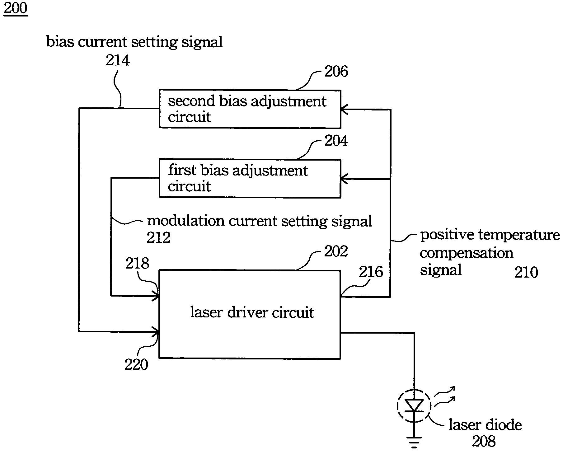
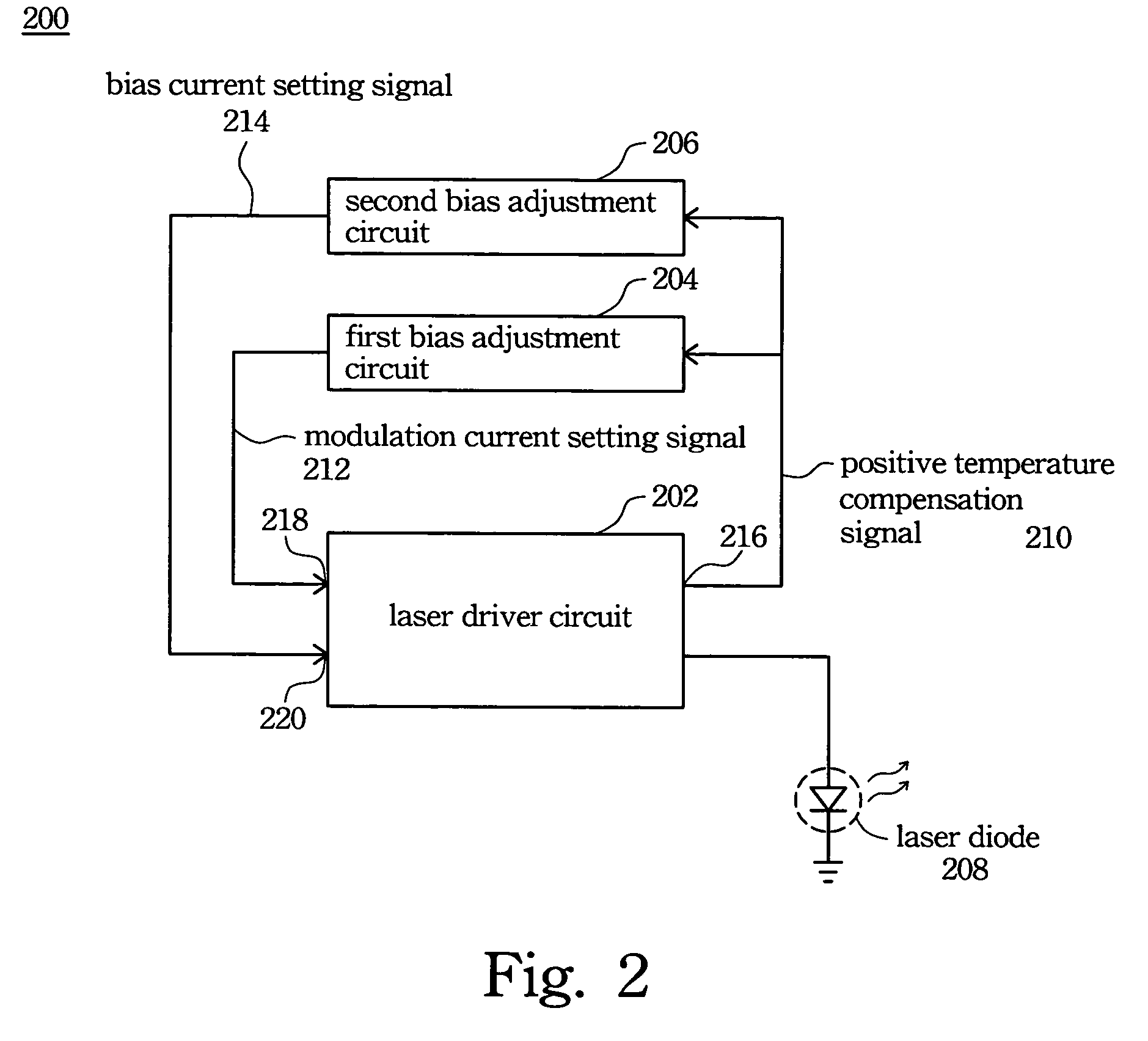
[0050]FIG. 2 is a block diagram of the first preferred embodiment of the laser transmitting apparatus 200. In this embodiment, a laser driver chip originally designed for continuous mode applications is used as the laser driver circuit 202. With external circuit modification, the laser driver circuit is used for burst mode applications. The requirements for selecting the laser driver circuit 202 are as follows. The laser driver circuit 202 must have a pulse width adjustment (PWA) input and a modulation current setting input. The laser driver circuit 202 must be able to generate a temperature compensation signal, such as a linearly positive or negative temperature-compensated voltage signal.

[0051]Moreover, the laser driver circuit 202 must be workable in open loop mode and have the functions of bias current setting and modulation current setting. When used in continuous mode, the data rate of the laser driver circuit 202 must be higher than 2.5 GHz.

[0052]For example, the Philips TZA ...

embodiment 2

[0061]When the relationship between the temperature compensation signal of the laser driver circuit and the temperature being inversely proportional, an external circuit modification is needed for the laser driver circuit 202, as shown in FIG. 3 and FIG. 4A. FIG. 3 is a block diagram illustrating the second preferred embodiment of the invention. When the relationship between the temperature compensation signal and the temperature is inversely proportional or the laser driver circuit does not have a temperature compensation signal, another temperature sensitive circuit 302 having the function of positive temperature compensation is needed. In FIG. 3, the laser transmitting apparatus 300 includes a laser driver circuit 202, a laser diode 208, and a temperature sensitive circuit 302. The laser diode 208 and the temperature sensitive circuit 302 are connected to the laser driver circuit 202, respectively.

[0062]The laser driver circuit 202 provides a driving current to the laser diode 20...

embodiment 3

[0064]When the relationship between the temperature compensation signal and the temperature is inversely proportional, there is another way to modify the external circuit, as shown in FIG. 4A. FIG. 4A is a block diagram illustrating the third embodiment of the invention. The laser transmitting apparatus 400 includes a laser driver circuit 202, a first bias adjustment circuit 402, a second bias adjustment circuit 404, and a laser diode 208. The first bias adjustment circuit 402, the second bias adjustment circuit 404, and the laser diode 208 are respectively connected to the laser driver circuit 202.

[0065]The laser driver circuit 202 provides a driving current to the laser diode 208 to generate a laser light. The laser driver circuit 202 generates a negative temperature compensation signal 407 in response to the environmental temperature. The relationship between the negative temperature compensation signal 407 and the environmental temperature is inversely proportional. The first bi...


PUM


Abstract

A method for making a laser driver circuit for burst mode is described. The method includes the following steps: First, a continuous mode laser driver circuit is selected, the chip having a temperature compensation output, a bias current setting input, and a reference current setting input. Next, the temperature compensation signal is converted to a reference current setting signal via a first bias adjustment circuit, and the reference current setting signal is input to the reference current setting input. Then, the bias current setting input is connected to ground via a second bias adjustment circuit. The reference current setting signal automatically adjusts the high level and the low level of the eye diagram of the laser according to the environmental temperature, so that the high level and the low level are kept stable to reduce the bit error rate in transmission.

Description

RELATED APPLICATIONS[0001]The present application is based on, and claims priority from, Taiwanese Application Number 93100938, filed Jan. 14, 2004, the disclosure of which is hereby incorporated by reference herein in its entirety.BACKGROUND[0002]1. Field of Invention[0003]The present invention relates to a design and fabrication method of a laser transmitting apparatus. More particularly, the present invention relates to a design and fabrication method of a laser transmitting apparatus for utilizing a continuous mode laser driver circuit for a burst mode transmission application where the high level and the low level of the laser power eye diagram are stably maintained so as to decrease the bit error rate in transmission process.[0004]2. Description of Related Art[0005]In the past, signals of optical fiber communication were usually transmitted in continuous mode. In continuous mode, since no signal can be interrupted during the transmission process, the optical fiber communicatio...

Claims


Application Information

Patent Timeline
Patent Type & Authority Patents(United States)
IPC IPC(8): H01S3/00H01S5/042H01S5/06H01S5/068
CPCH01S5/06804H01S5/0427H01S5/0428
Inventor CHANG, YI-YANG
Owner ASIA OPTICAL CO INC
Why Eureka
Try Eureka