
Weapon aiming device

a technology of aiming device and weapon, which is applied in the direction of sighting device, weapon components, weapons, etc., can solve the problems of large aim point, large aim point, and large size of aim point,

Inactive Publication Date: 2008-02-05
L 3 COMMUNICATIONS INSIGHT TECHNOLOGY INCORPORATED
View PDF44 Cites 28 Cited by
  • Summary
  • Abstract
  • Description
  • Claims
  • Application Information

AI Technical Summary

Problems solved by technology

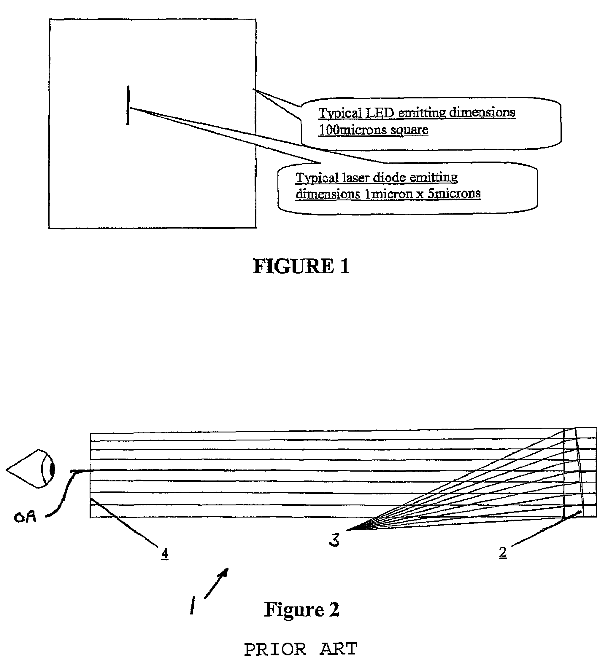
Because the LED has a relatively large emitting area and practical transmission and machining capability limitations limit how small a pinhole can be used, the resulting aim point is relatively large in size.
Such a large aim point is undesirable and impairs accuracy especially when aiming at a relatively small target or a target at a relatively long distance.
Red dot sights utilizing tritium (a radioactive isotope) exist, but suffer because the brightness can not be increased during the day and decreased during the night to be compatible with night vision devices.
The result is the target scene has an undesirable blue tint.
Not only does this blue tint cause the scene to look unnatural, it also impairs one's ability to use the sight with two eyes open because one eye sees the target scene in normal color while the eye seeing the target scene through the sight sees a bluish scene.
The blue tint also makes target acquisition difficult in low light conditions such as dusk or dawn because a lack of light transmission.
Depending on the nature of the reflective coating, the coating impairs the transmission of light in a portion of the electromagnetic spectrum that the night vision device is sensitive thereby reducing the performance capabilities of the night vision device, in turn affecting the ability of the operator to detect and direct fire on the target.
This can be quite distracting.
The large aim point and the distorted color of the target scene are two major limitations of existing red dot sights.
This results in a loss of aiming accuracy.
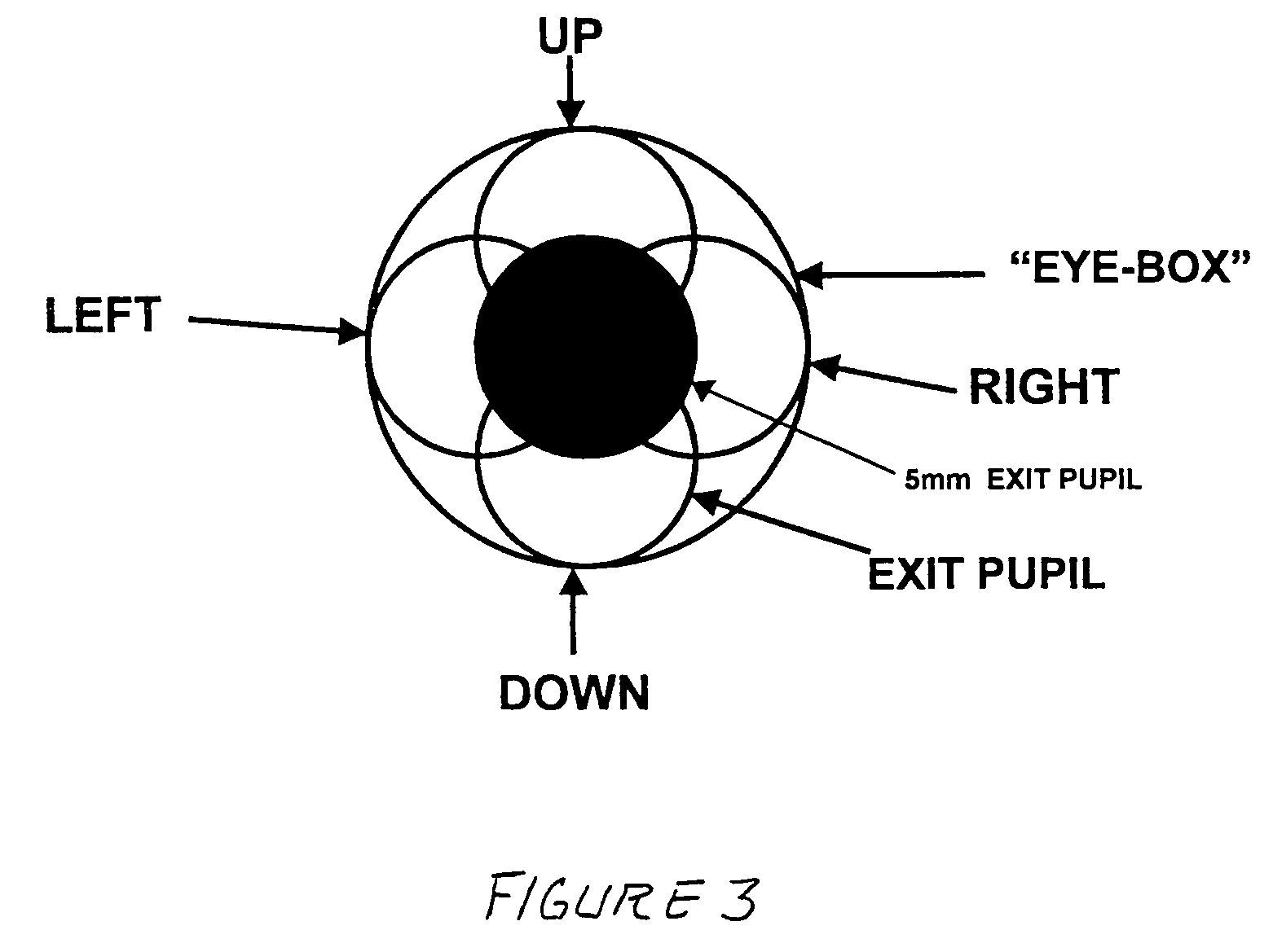
Also, since different shooters hold their eye differently relative to the sight, no single boresight or zero setting of the sight is suitable for all users.

Method used


Image

  • Weapon aiming device
  • Weapon aiming device
  • Weapon aiming device

Examples


Embodiment Construction

[0021]FIG. 1 is a relative comparison of the emitting dimensions of a light emitting diode (LED) versus a laser diode. A typical LED has an emitting dimension of 100 microns square or larger whereas a typical laser diode has an emitting dimension of 1 micron×5 microns. When using an LED in a close quarter combat optics, for example a red dot sight, a light blocking plate with an aperture is placed in front of the LED to reduce the size of the exiting light beam. The aperture size is approximately 0.0005″ to 0.002″ in diameter. The aperture is typically formed in the plate, as a secondary step after molding or machining, with a laser due to the small aperture size requirement. The plate with this secondary step can add significant cost to the sight. The light emitted from the LED that is blocked by the plate (>95%) is trapped inside the optics housing and adds heat within the enclosure and wastes energy and battery or electric source life. Close quarter combat sights are run off of b...


PUM


Abstract

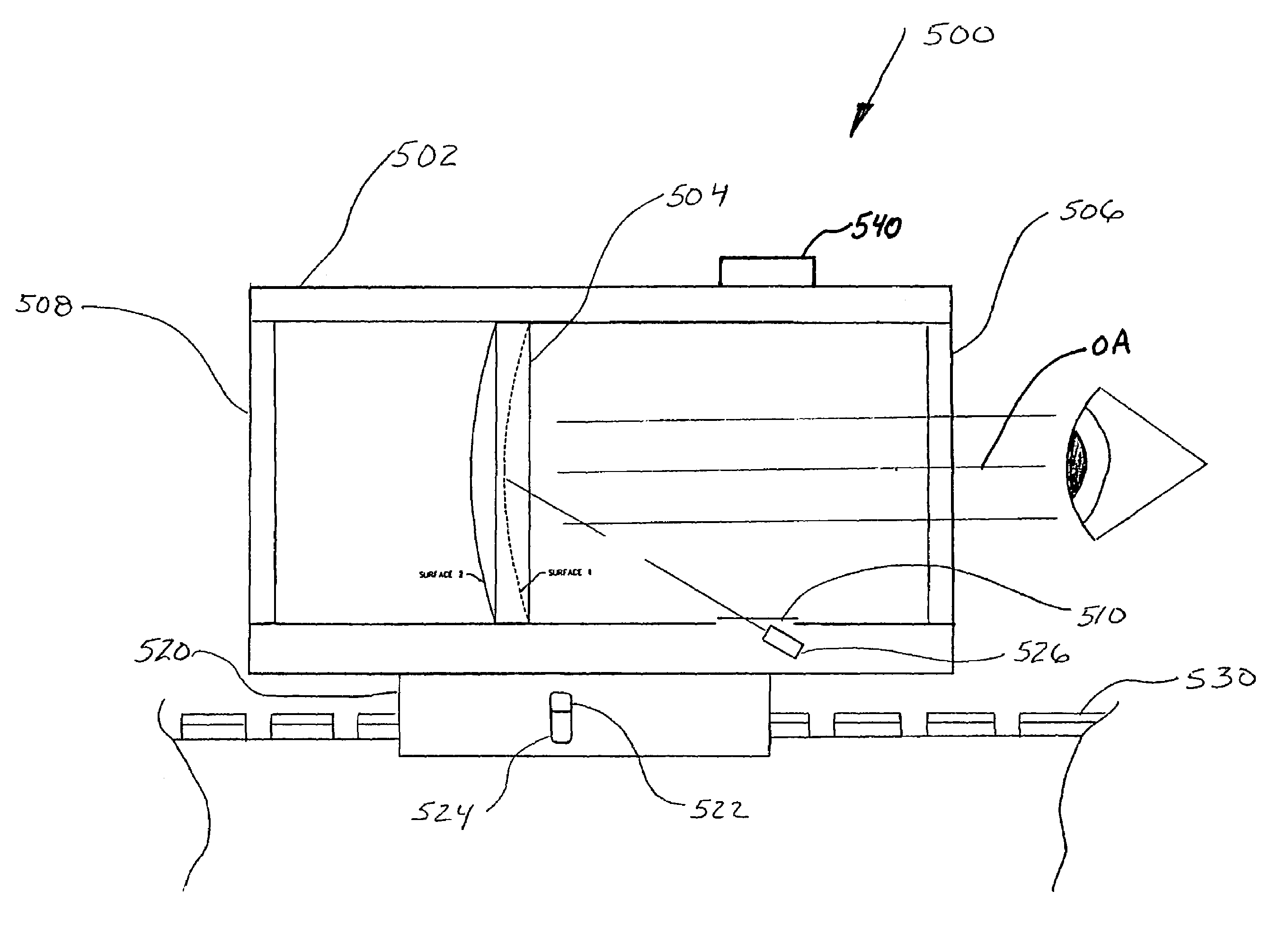
A weapon aiming system may utilize a laser diode and a reflective coating on an optical element to generate a red dot aim point for a shooter with a bright view to the target with minimal color distortion. The optical element may utilize an off-axis parabolic lens to reduce parallax to improve sighting accuracy. The weapon aiming system may utilize visible and infrared aim lasers that are coaligned to simplify boresighting of the weapon and to simplify target acquisition. The weapon aiming system may include a magnifier and a sight being disposed along a longitudinal rail of a weapon in a position with the close quarter combat sight being disposed between the magnifier and the weapon muzzle.

Description

CROSS-REFERENCE TO RELATED APPLICATIONS[0001]The present application claims the benefit of U.S. provisional patent application Ser. No. 60 / 568,528, filed May 6, 2004, the disclosure of which is incorporated herein by reference in its entirety.TECHNICAL FIELD[0002]This invention relates to a weapon-aiming device, and more particularly to a weapon-mountable red dot sight.BACKGROUND OF THE INVENTION[0003]In close quarter combat, typically in the ranges of 2-800 meters, soldiers are required to rapidly acquire, identify, and accurately fire on enemy targets. Soldiers may use weapon-mounted sights with visible and infrared light sources to assist in the aiming process during daytime and nighttime missions. These sights may be mounted on handheld weapons such as the M4A1 carbine and other small arms and are used to provide better target observation, illumination, and marking.[0004]Traditional weapon-mounted sights utilize red dot sights that incorporate a light emitting diode (LED) as a s...

Claims


Application Information

Patent Timeline
Patent Type & Authority Patents(United States)
IPC IPC(8): F41G1/38F41G1/34
CPCF41G1/30F41G1/38
Inventor GRAUSLYS, RICHARD P.HARDING, ALLEN R.
Owner L 3 COMMUNICATIONS INSIGHT TECHNOLOGY INCORPORATED
Learn More