Press oven including an intermediate body, and method for use

a press oven and intermediate body technology, applied in the field of press ovens, can solve the problems of pressing stamps that cannot be easily removed, press stamps remain slightly stuck to ceramics, and press stamps that must exert considerable pressure, etc., to achieve the effect of reducing the operating speed of the press stamp of the press oven, reducing the operating cost, and reducing the cost of capital

Inactive Publication Date: 2008-02-05
IVOCLAR VIVADENT AG
View PDF9 Cites 8 Cited by
  • Summary
  • Abstract
  • Description
  • Claims
  • Application Information

AI Technical Summary

Benefits of technology

[0011]The present invention offers a solution to the challenge of providing a press oven, an intermediate body, and, as well, a process for the operation of a press oven, which collectively permit a rapid and stress-minimized press cycle with minimum capital costs whereby, however, the operational speed of the press stamp of the press oven is not too greatly limited.
[0012]The inventive press oven is characterized by the targeted use of a material for the intermediate body that has a heat conducting capability less than that of the material that encircles it. In this connection, there occurs a clear reduction of the abrupt heat transition between the pre-heated blank and the cold press stamp. Surprisingly, by the use of these measures, stress cracks in the blank due to the sudden temperature reduction are avoided. While the heretofore deployed blanks exhibited, on the sides thereof turned toward the press stamp, stress cracks as a result of the intensive contacts with the press stamp, with such stress cracks having foreclosed the possibility to use these portions of the press stamp, that is, the upper portion of the blank, for the press stamp process, the present invention, conversely, ensures a uniform material quality over the entire blank, even if a rapid process execution is performed during which there is insufficient time to pre-heat the cold press stamp.
[0013]In accordance with the present invention, it is particularly favorable, as well, if the material of the intermediate body is chosen so as to have a reduced hardness relative to that of ceramic. The material need not be extended over the entire height of the intermediate body; for the desired buffer effect, an extension of the material over a portion of the height such as, for example, half the height, is sufficient. Via this surprisingly simple measure, the pressure peaks that are introduced via the press stamp can be drastically reduced. In accordance with the present invention, it is particularly advantageous that, as well, the time lags (dead time) introduced via the press stamp operation itself and its mass are compensated for, in that the decidedly small intermediate body buffers, as well, the inertia of the press stamp during rapid movement of the press stamp.

Problems solved by technology

In connection with such press ovens but, as well, in connection with press ovens that do not have a sealing-off piston—by which, therefore, the press stamp itself applies pressure directly on the blank—the problem exists that the press stamp remains slightly stuck to the ceramic.
With respect to the approach disclosed in EP-A1-231 773, a problem additionally exists that the sealing-off piston and the blank intensively interconnect with one another at the deformation temperature of the ceramic and, thus, can only be released following an extensive stress relieving working.
One must then practically separate the entire sealing-off piston with a diamond cutter which is time-consuming and wear-intensive.
A further problem resides in the fact that the press stamp must exert a considerable pressure to ensure that the ceramic of the blank, which has become soft via the increase in the temperature, penetrates into the branching of the mold cavity in which the restoration pieces should be configured.
This leads to a significant increase in the pressure that, in particular, strongly loads the muffle and can lead to the occurrence of spalling locations that detract from the required precision for the production of the dental restoration pieces.
Such systems must compensate for, as well, the dead times of the system and are, consequently, expensive.
This approach, however, requires as well a compensation of the dead time in the control system, whereupon such a control system is complex and is, as well, particularly difficult to calibrate.

Method used


Image

  • Press oven including an intermediate body, and method for use
  • Press oven including an intermediate body, and method for use
  • Press oven including an intermediate body, and method for use

Examples


Embodiment Construction

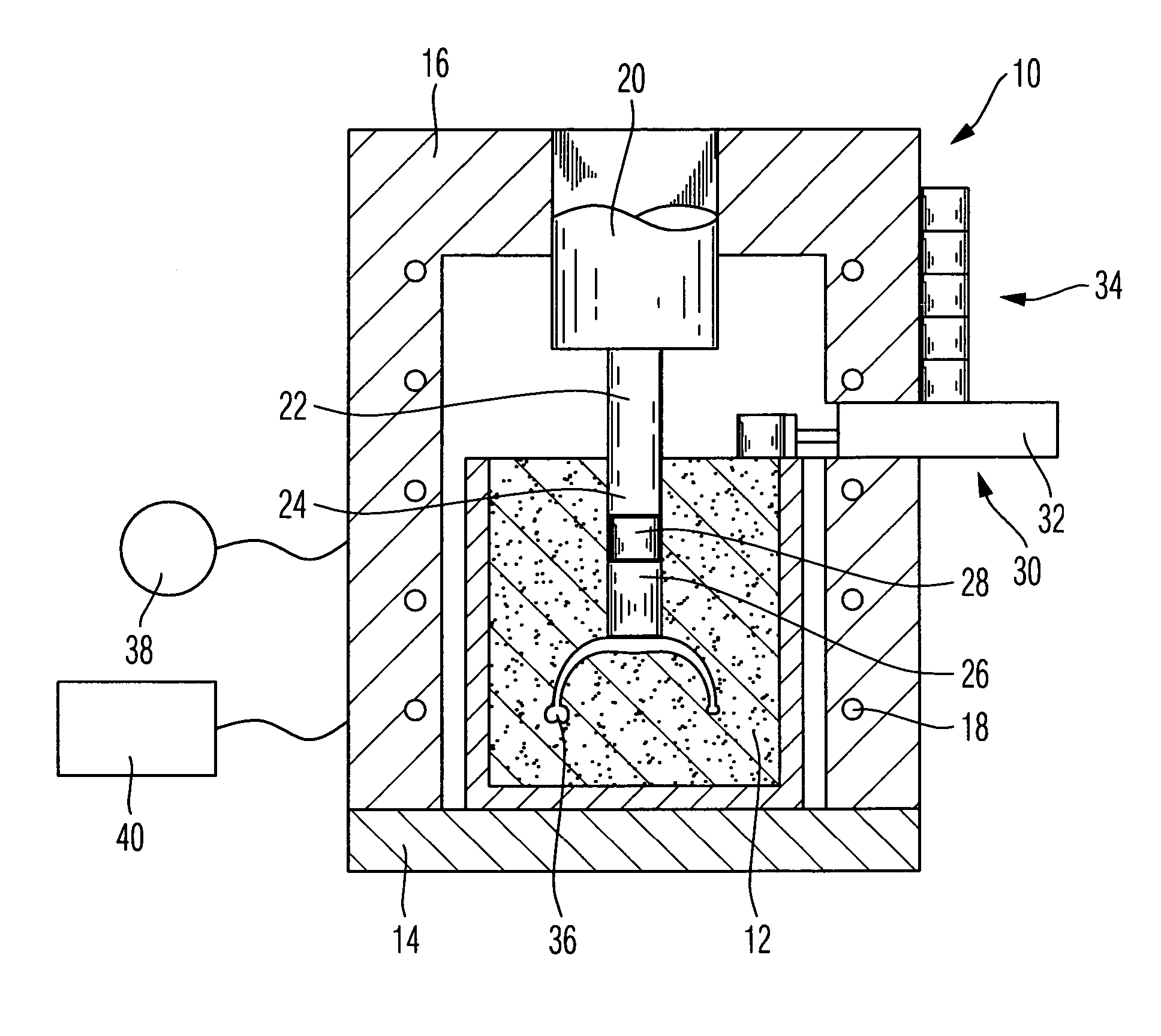
[0050]The press oven 10 shown in FIG. 1 is configured for the receipt of a muffle 12. The press oven comprises a base plate 14 and a press oven hood 16 that receives the heating element 18 of the press oven 10. A press piston 20 is moved in a known manner centrally and from above within the press oven hood 16, the piston transitioning into a press stamp 22 that is in a position to penetrate into a feed channel 24 located in the muffle 12.

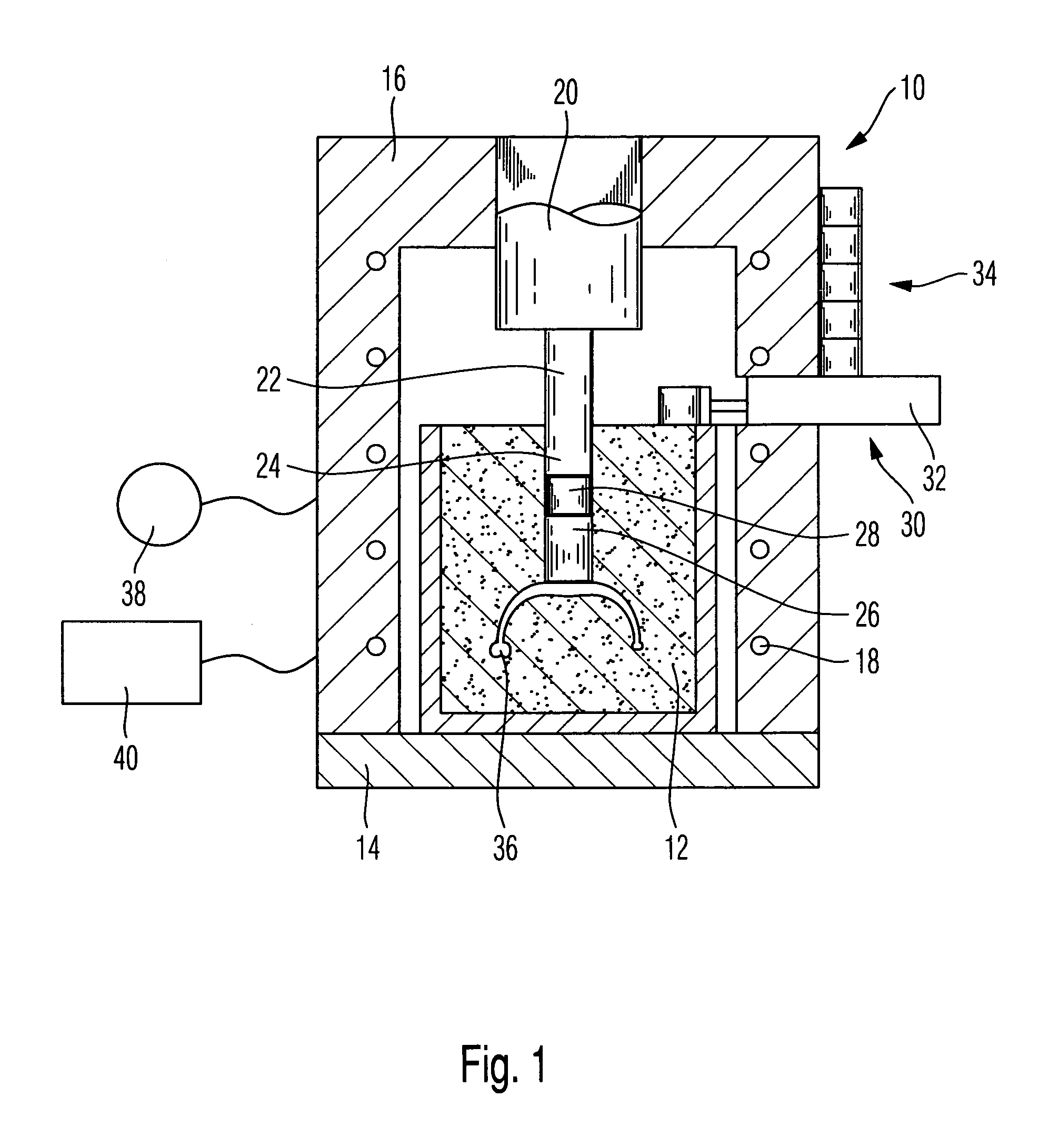
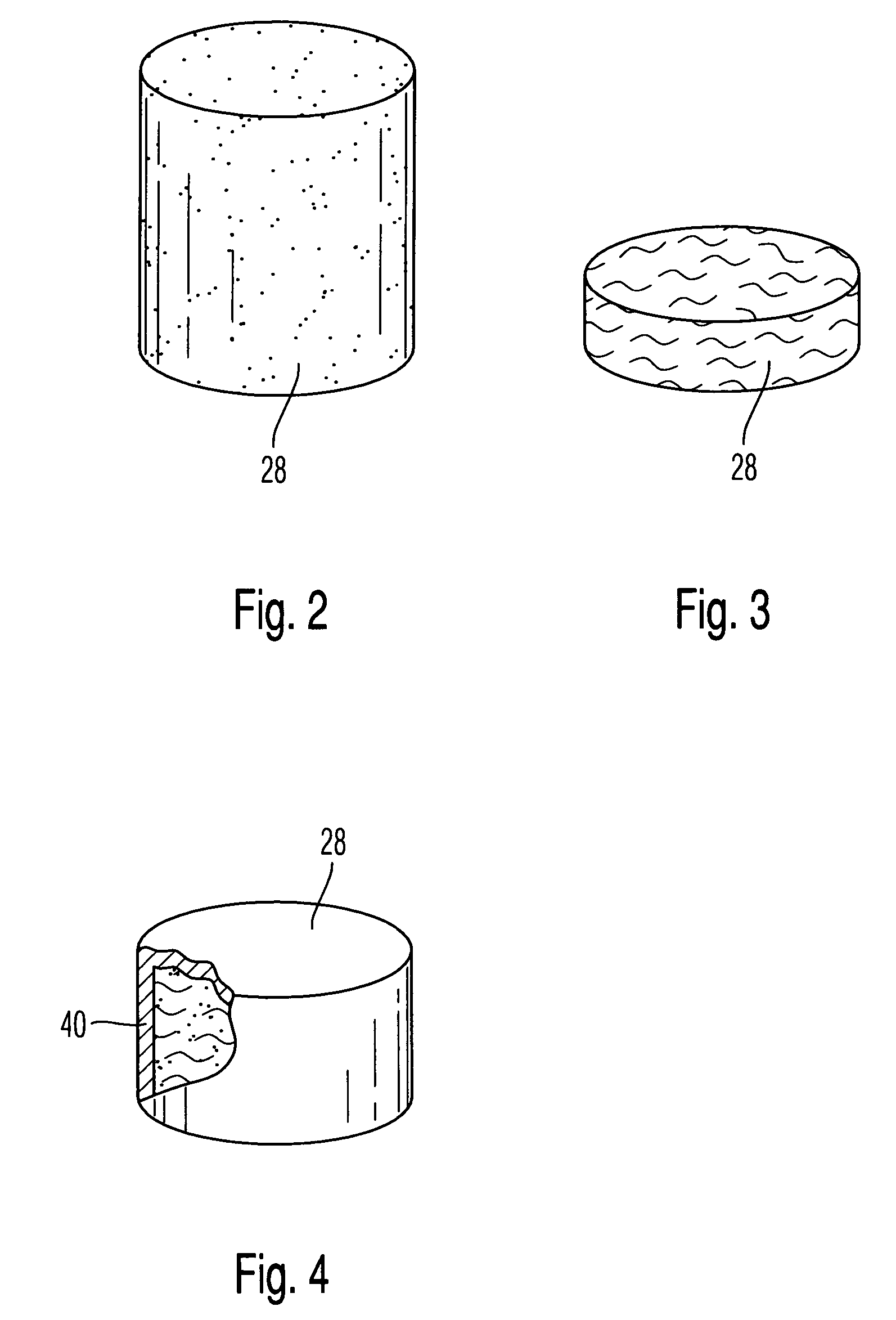
[0051]In connection with the production of a dental restoration piece, a cylindrically shaped blank 26 of dental material is disposed in the feed channel. In accordance with the present invention, an inventive intermediate body 28 is thereafter disposed in the feed channel 24 before the press stamp 22 is traveled downwardly.

[0052]The blank 26 can be comprised either of a ceramic mass such as, for example, aluminum oxide ceramic, a zirconium oxide ceramic, or a mixture of these or, as well, can comprise a metal alloy.

[0053]In accordance with this inv...


PUM

PropertyMeasurementUnit
melting temperatureaaaaaaaaaa
temperatureaaaaaaaaaa

Abstract

A press oven, especially for the pressing of dental material, includes a press stamp via which pressure can be exerted on a blank in a matrix mass of a muffle. An intermediate body is positionable between the press stamp and the blank and the heat conducting capability of the intermediate body (28) is less than that of the blank (26), the press stamp (22) or the matrix mass of the muffle (12).

Description

CROSS-REFERENCE TO RELATED APPLICATIONS[0001]This application claims foreign priority benefits under 35 U.S.C. §119 from German patent application Ser. No. 10 2004 013 668.8 filed Mar. 19, 2004.TECHNICAL FIELD[0002]The present invention relates to a press oven, to an intermediate body for a press oven, and a process for the operation of a press oven.BACKGROUND OF THE INVENTION[0003]A press oven of this type is disclosed, for example, in EP-A1-231 773. In a press oven of this type, a substantially disk- or flat-cylinder shaped sealing-off piston is pressed downwardly via a press stamp (or piston rod) to apply pressure to a blank that melts as the pressure is exerted thereon. The sealing-off piston is comprised of ceramic and has a diameter that corresponds to the diameter of a feed channel for the blank. Also, the blank is comprised of a ceramic whose consistency and material properties are selected to achieve the desired restoration result.[0004]In connection with such press ovens b...

Claims


Application Information

Patent Timeline
Patent Type & Authority Patents(United States)
IPC IPC(8): B21D37/16A61C19/00A61C13/20B28B3/02B28B11/24F27B17/02
CPCA61C13/20
Inventor FOSER, HANS-PETER
Owner IVOCLAR VIVADENT AG
Why Eureka
Try Eureka