Projection type video display apparatus

a video display and projection technology, applied in the direction of color television details, television systems, instruments, etc., can solve the problems of the position of the person cannot be detected, and the sudden change in the amount of projected light, etc., to achieve the effect of reducing the brightness of the projected video, and dazzling the effect of the person who exists within the projection video area

Inactive Publication Date: 2008-02-05
SANYO ELECTRIC CO LTD
View PDF19 Cites 28 Cited by
  • Summary
  • Abstract
  • Description
  • Claims
  • Application Information

AI Technical Summary

Benefits of technology

[0013]According to the first projection type video display apparatus, when the person exists within the projected video area, the state of the video is changed, thereby allowing a dazzling impression on the person who exists within the projected video area to be reduced.
[0027]According to the third projection type video display apparatus, a dazzling impression on the person who exists within the projected video area can be reduced. Further, a video signal can be changed only within a range in which the person exists, thereby making it possible to reduce interference with a presentation.

Problems solved by technology

As a result, it is erroneously detected that the person exists in the vicinity of the projection type video display apparatus irrespective of the fact that no person exists within the projected video area, so that the amount of the projected light is adjusted.
Therefore, a person who is watching a video feels uncomfortable by a sudden change in the amount of the projected light.
As a result, every time the person who appears in the film is projected as the character on the video, the luminance of video light around the character is changed irrespective of the fact that no person exists in front of the projection type video display apparatus, so that a person who is watching the film feels uncomfortable.
Although in this configuration, the existence of the person can be detected, however, the position where the person exists cannot be detected.
Not only an area where the person exists but also the luminance of the whole of a video is changed, so that a person who is watching a film or the like feels uncomfortable.

Method used


Image

  • Projection type video display apparatus
  • Projection type video display apparatus
  • Projection type video display apparatus

Examples


first embodiment

[1] First Embodiment

[0056]Referring now to FIGS. 1 to 7, a first embodiment of the present invention will be described.

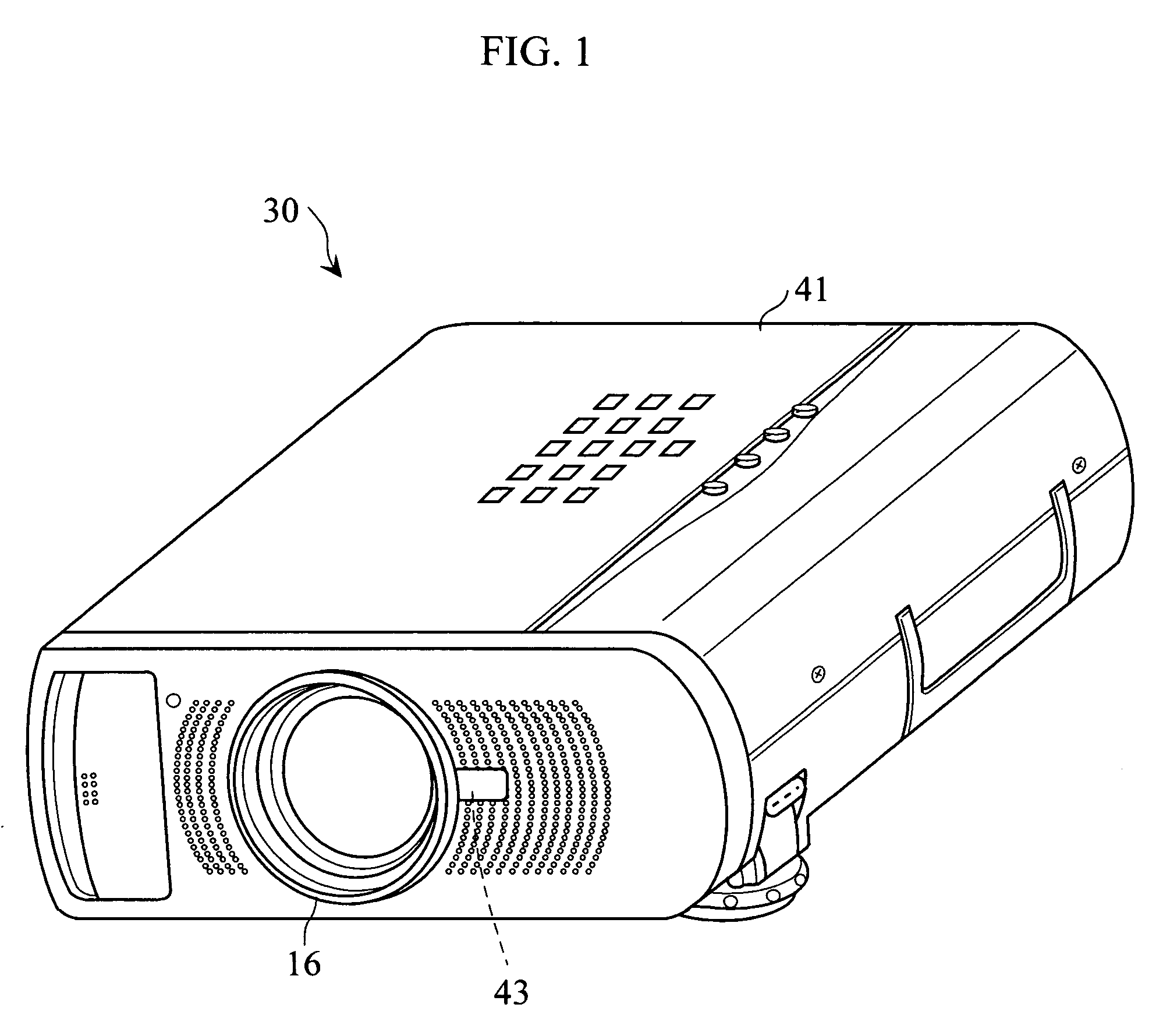
[0057]FIG. 1 is a diagram showing the appearance of a three-panel type liquid crystal projector 30.

[0058]Within a main body case 41 in the liquid crystal projector 30, an optical system 42 (see FIG. 2) leading to a projection lens 16 (see FIGS. 1 and 2) from a light source 1 (see FIG. 2), described later, is arranged.

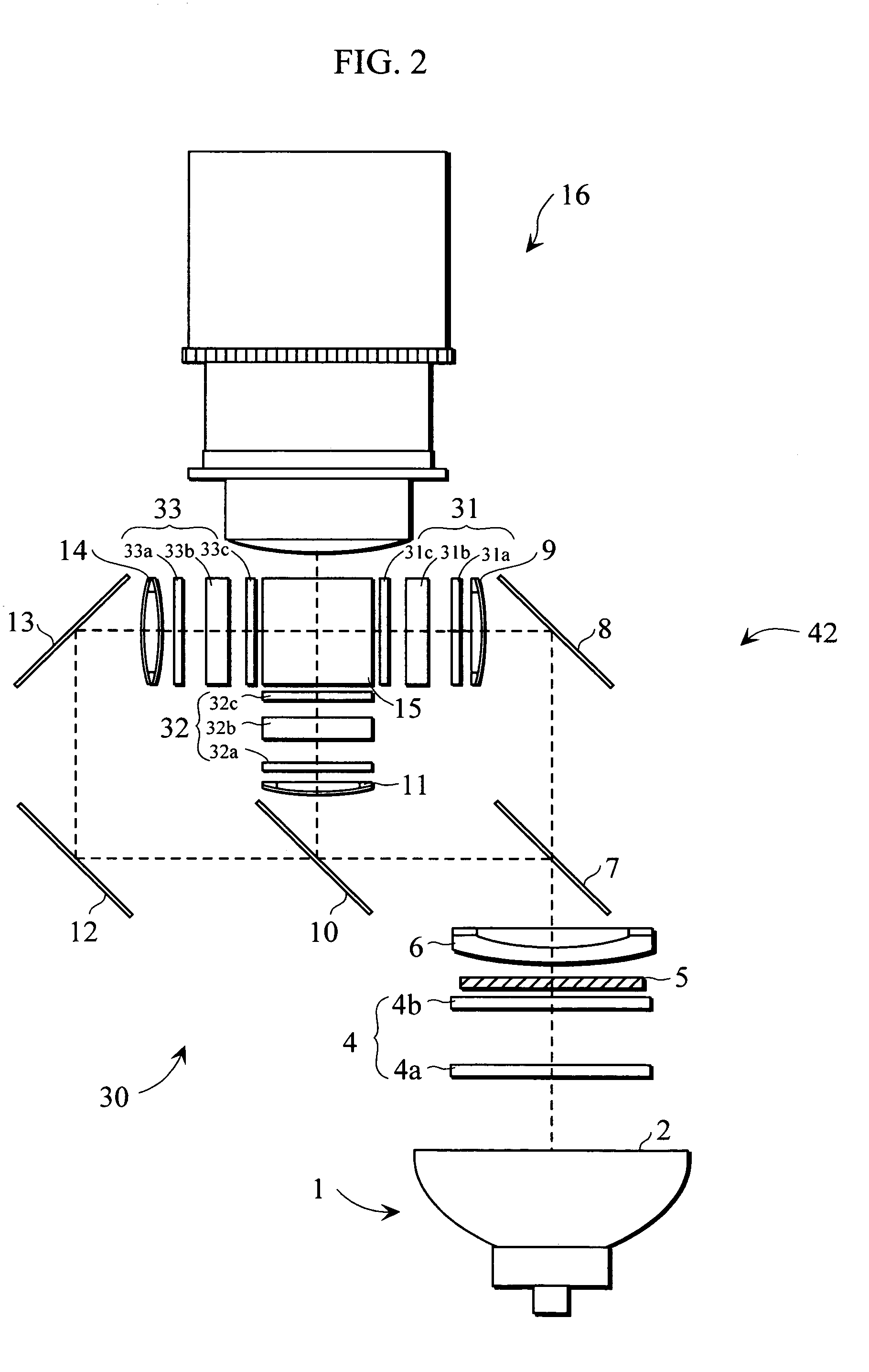
[0059]FIG. 2 is a diagram showing the configuration of the optical system 42 arranged within the main body case 41.

[0060]A light emitter in the light source 1 is composed of a ultrahigh pressure mercury lamp, a metal halide lamp, a xenon lamp, etc. Light irradiated from the light emitter in the light source 1 is emitted as parallel light by a parabolic reflector 2, and is introduced into an integrator lens 4.

[0061]The integrator lens 4 comprises a pair of lens groups (fly eye lenses) 4a and 4b, and so adapted that each of lens portions introduces light ...

second embodiment

[2] Second Embodiment

[0079]Referring now to FIGS. 8 to 11, a second embodiment of the present invention will be described.

[0080]The second embodiment is approximately the same as the first embodiment except that a projected video range is variable and a person detection range of a person detection sensor 43 is adjustable.

[0081]FIG. 8 illustrates the configuration of an optical system 42′ arranged within a main body case 41. In FIG. 8, the same components as those shown in FIG. 2 are assigned the same reference numerals and hence, the description thereof is not repeated.

[0082]Although the projection lens 16 is fixed in the first embodiment, a projection lens 16 in the second embodiment comprises a lens driving motor 22 for moving the projection lens 16 back and forth in order to enlarge or reduce a projected video.

[0083]As shown in FIGS. 10 and 11, the person detection sensor 43 is covered with a cylinder 50 held so as to be movable back and forth in the main body case 41. In order t...

third embodiment

[3] Third Embodiment

[0088]Referring now to FIGS. 12 to 23, a third embodiment of the present invention will be described.

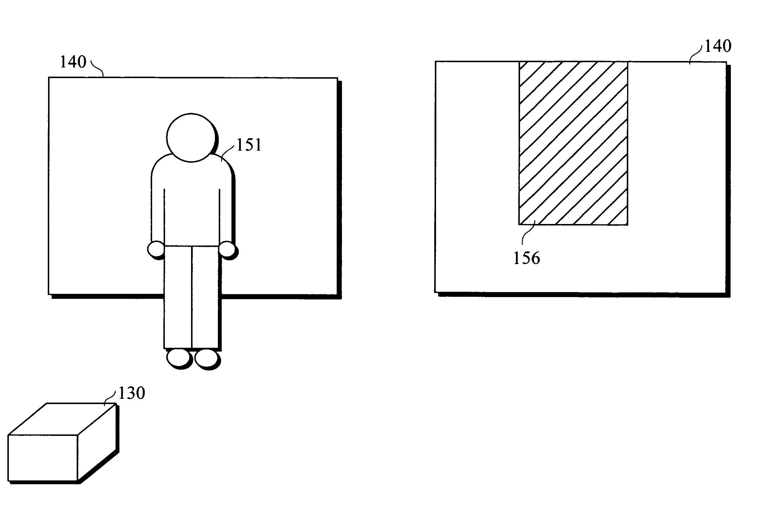
[0089]FIG. 12 is a diagram showing the appearance of a three-panel type liquid crystal projector 130.

[0090]Within a main body case 141 in the liquid crystal projector 130, an optical system 142 leading to a projection lens 16 (see FIGS. 12 and 13) from a light source 12 (see FIG. 13), described later, is arranged.

[0091]FIG. 13 is a diagram showing the configuration of the optical system 142 arranged within the main body case 141. In FIG. 13, the same components as those shown in FIG. 2 are assigned the same reference numerals and hence, the description thereof is not repeated.

[0092]Also in the third embodiment, a projection lens 16 comprises a lens driving motor 22 for moving the projection lens 16 back and forth in order to enlarge or reduce a projected video, as in the second embodiment.

[0093]As shown in FIG. 12, person detection sensors 143a and 143b serving as...


PUM


Abstract

A projection type video display apparatus in which a display device transmits light emitted from a light source to project a video written into the display device is characterized by comprising person detection means for detecting a person who exists within a projected video area, and control means for changing the state of the projected video when the person detection means detects the person.

Description

BACKGROUND OF THE INVENTION[0001]1. Field of the Invention[0002]The present invention relates to a projection type video display apparatus such as a liquid crystal projector.[0003]2. Description of the Background Art[0004][1] An example of a projection type video display apparatus is one comprising distance detection means for detecting the distance between a person who exists within a projected video area (within an optical path of projected light) and the projection type video display apparatus to prevent the person from feeling dazzling by adjusting the amount of projected light when the distance detection means detects that the person exists in the vicinity of the projection type video display apparatus. The distance detection means is composed of a light receiving element (an optical sensor), to presume the distance between the person and the projection type video display apparatus by the amount of light reflected from the person that has been received by the light receiving el...

Claims


Application Information

Patent Timeline
Patent Type & Authority Patents(United States)
IPC IPC(8): G03B21/14G03B21/26H04N5/74
CPCG03B21/26H04N5/74H04N5/7441
Inventor KAISE, NAOKIMURAOKA, KOJIKIRIMURA, TORU
Owner SANYO ELECTRIC CO LTD
Why Eureka
Try Eureka