Reducing leakage current in guide wire assembly

a technology of leakage current and guide wire, which is applied in the direction of coupling device connection, electrotherapy, medicine/surgery connector, etc., can solve problems such as leakage current, and achieve the effect of reducing leakage current in the guide wire assembly

Inactive Publication Date: 2008-02-05
ST JUDE MEDICAL COORDINATION CENT
View PDF8 Cites 39 Cited by
  • Summary
  • Abstract
  • Description
  • Claims
  • Application Information

AI Technical Summary

Benefits of technology

[0008]A further object is to provide a more reliable guide wire assembly.
[0011]According to a first aspect of the present invention, there is provided a method comprising the steps of applying a guard potential to said at least one insulator, which guard potential is arranged to reduce a potential difference across the insulator such that leakage current is reduced.
[0012]According to a second aspect of the present invention, there is provided a device comprising an electrode arranged to apply a guard potential to said at least one insulator, which guard potential is arranged to reduce a potential difference across the insulator such that leakage current is reduced.
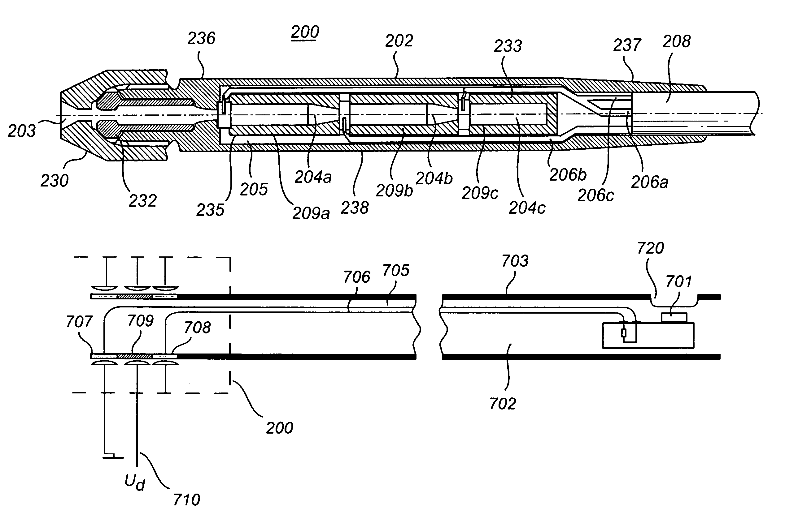
[0014]In a guide wire assembly comprising a miniature sensor for measuring physiological variables, leads extending along, or inside, the guide wire carry measurement signals from the sensor via connectors to an external device, such as a monitor, for display and / or further processing. In the following example, it is assumed that a first lead carries a pressure signal and a second lead is set to a reference potential, typically ground. Note that the lead being coupled to a reference voltage, such as ground, is not regarded as a signal lead, as no actual measurement signal is transferred via that particular lead. In case two leads are utilized, there are typically two corresponding conductor members arranged at the connector end of the guide wire for coupling the sensor signal carried by one of the leads to the external monitor, and for connecting the other lead to a common ground. An insulating guide wire sheath extends along the guide wire and ends at a first conductor member, which couples the pressure signal out of the guide wire assembly. Adjacent to the first conductor member is the insulator separating the first conductor member from a second conductor member, which is connected to ground, or some other appropriate reference potential. As previously described, bodily fluids will deteriorate the insulating capacity of the insulator, but by applying the guard potential to the insulator by means of an electrode, the potential difference across the insulator, with respect to the adjacently located conductor member to which the signal carrying lead is connected, is reduced and the corresponding leakage current will be reduced accordingly. This is highly advantageous, as the problem relating to unreliable sensor values due to leakage currents in the connector is eliminated.
[0020]The potentials at the first and second conductor members generally have the same voltage level, which has the effect that no leakage current will flow through the second insulator separating the first and second leads, since no potential difference is present across the second insulator. However, due to bodily fluids there will be a potential difference across the first insulator located between the first conductor member and the guide wire sheath, as well as across the third insulator located between the second conductor member and the third, grounded conductor member. As a consequence, there will be leakage currents via the first and the third insulators, respectively.
[0027]Typically, the device for reducing leakage current in the guide wire assembly according to the present invention is arranged at a female connector for the guide wire assembly, such that the guard potential is applied to the insulator(s) when the male connector arranged at the connector end of the guide wire is inserted into the female connector to provide signals transferred via the signal leads to an external device.

Problems solved by technology

Leakage currents may also be due to general deteriorations in insulating capacity, for example arising from manufacturing defects.

Method used


Image

  • Reducing leakage current in guide wire assembly
  • Reducing leakage current in guide wire assembly
  • Reducing leakage current in guide wire assembly

Examples


Embodiment Construction

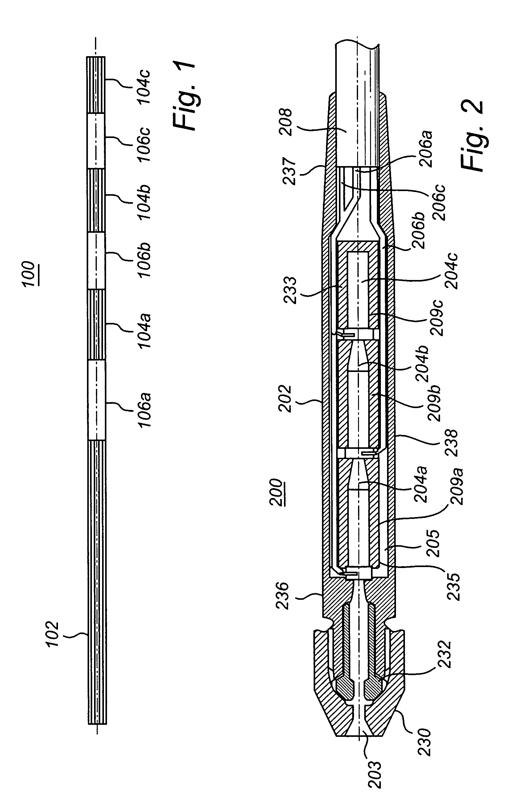
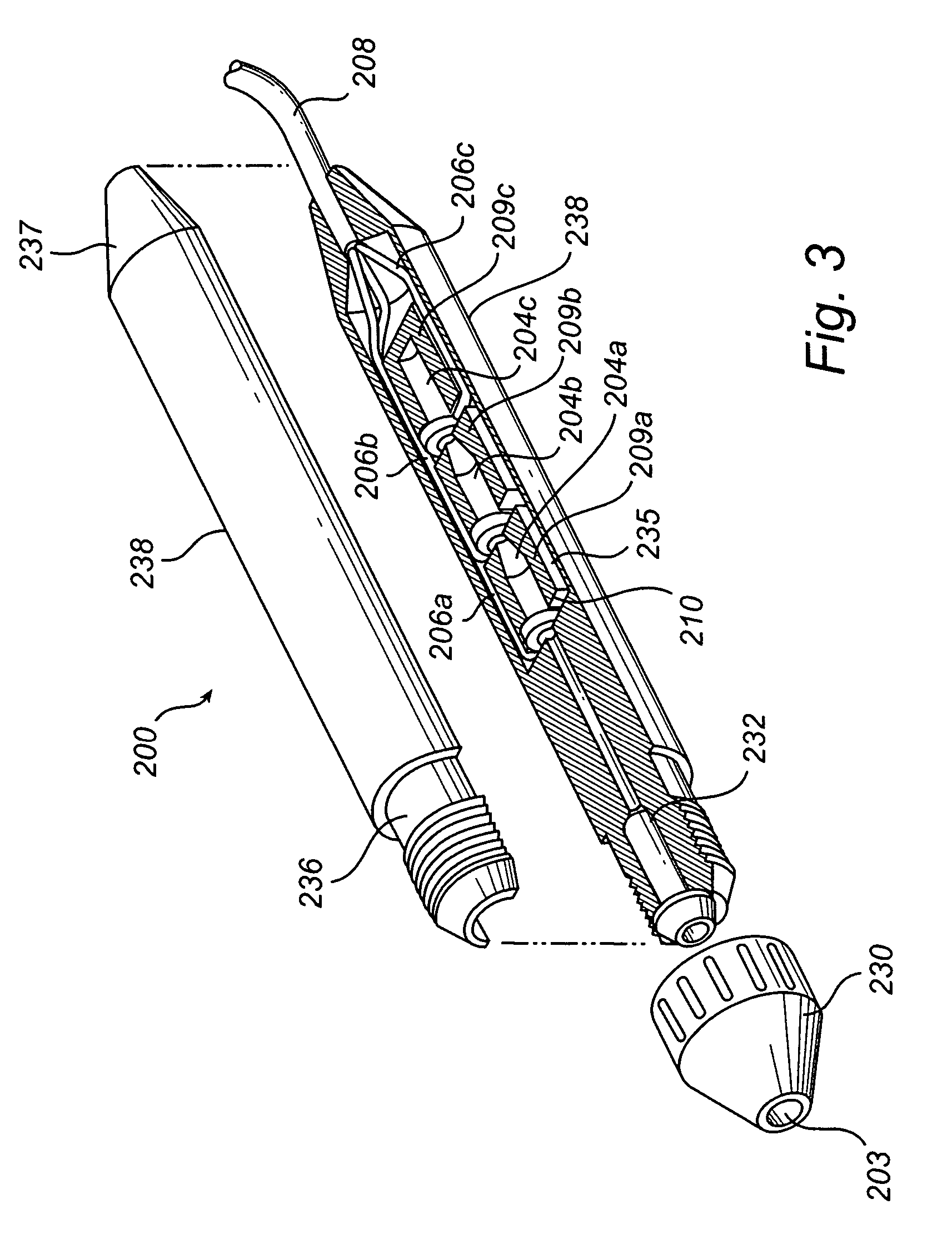
[0042]In FIG. 1, a male connector 100 is depicted. It is located at the proximal end of a guide wire 102, the guide wire and the connector having essentially the same diameter. The male connector 100 is comprised of three conductive cylindrically shaped members 104a, b and c, one for each lead required in the guide wire 102, separated by means of insulating spacers 106a, b and c, referred to as insulators. The insulators are preferably made of a molded polymer material. The insulating material can be, for example, a two-component epoxy adhesive. The insulators 106a, b and c perform the function in the assembled male connector of spacing apart the core wire from the conductor members 104a, b and c. Thus, the conductor members are electrically insulated from the core wire. They also space the conductor members apart from each other and the sheath of the guide wire, in case the sheath is conductive. On insertion of the male connector in a female connector (shown in FIG. 2), each of the...


PUM


Abstract

The present invention relates to a method and a device for reducing leakage current in a guide wire assembly having conductor members (707, 708) arranged at a connector end of the guide wire (702) to provide electrical contact with electrical leads (705, 706) of the guide wire and to provide signals transferred via the electrical leads to an external device, said conductor members being separated by at least one insulator (709). An idea of the present invention is to minimize leakage current via the at least one insulator. When a physician places the guide wire into an appropriate location in the body, a male connector (100) of the guide wire may be contaminated by, for example, dirt, fat, moisture, etc., which is attached to the physician's fingers and deposited onto the male connector. An electrode (710) mounted at the female connector is used to apply a guard potential (Ud) to the insulator (709) to reduce potential difference and thereby reduce current leakage between members (707, 708).

Description

TECHNICAL FIELD OF THE INVENTION[0001]The present invention relates to a method and a device for reducing leakage current in a guide wire assembly having conductor members arranged at a connector end of the guide wire to provide electrical contact with electrical leads of the guide wire and to provide signals transferred via the electrical leads to an external device, said conductor members being separated by at least one insulator.BACKGROUND ART[0002]Guide wires are generally known in the art. Their use is, for example, in connection with treatment of coronary disease. As is conventional, a contrast media is used in connection with an x-ray of a blood vessel to show occlusion, however, without showing a cross section of a stenosis. Complicating the diagnosis of the problem is that different patients have different blood flow. Measurement of blood pressure is a way to diagnose the significance of the stenosis. In practice, a distal end of the guide wire is inserted into the body, fo...

Claims


Application Information

Patent Timeline
Patent Type & Authority Patents(United States)
IPC IPC(8): A61N1/375H01R24/04H01R24/58
CPCH01R13/5224H01R2201/12
Inventor TULKKI, SAULI
Owner ST JUDE MEDICAL COORDINATION CENT
Why Eureka
Try Eureka