Pulse wave monitoring device

a monitoring device and pulse wave technology, applied in the field of pulse wave monitoring devices, can solve the problems of difficult to collect plethysmograms with stability and reproducibility, complicated measurement, and inability to simply conduct the measuremen

Active Publication Date: 2008-02-05
OMRON HEALTHCARE CO LTD
View PDF19 Cites 20 Cited by
  • Summary
  • Abstract
  • Description
  • Claims
  • Application Information

AI Technical Summary

Benefits of technology

[0014]It is an object of the present invention to provide a pulse wave monitoring device for supporting a diagnosis by presenting characteristic parameters of a pulse wave as information of a circulatory system other than blood pressure to a doctor without deteriorating simplicity of measurement.
[0017]Preferably, a first characteristic point of the characteristic points corresponds to a peak of a traveling wave component of the detected pulse wave and a second characteristic point of the characteristic points corresponds to a peak of a reflection wave component of the detected pulse wave, the reflection wave component being generated as a result of a reflection of the traveling wave component, and the index is a ratio of amplitudes of the pulse wave at the first and second characteristic points. The index can be, therefore, calculated easily.
[0018]Preferably, a first characteristic point of the characteristic points corresponds to a traveling wave component of the detected pulse wave and a second characteristic point of the characteristic points corresponds to a reflection wave component of the detected pulse wave, the reflection wave component being generated as a result of a reflection of the traveling wave component, and the index is a time difference between the first and the second characteristic points. The index can be, therefore, calculated easily.
[0026]The display unit preferably shows the calculated indices and the measured blood pressures in the chronological order. The indices and the blood pressures calculated and measured in the past are related with each other so as to be displayed in the chronological order. For this reason, the doctor checks the displayed contents so as to understand the state transition of the circulatory system represented by a correlation between the blood pressures and the indices of the subject according to passage of time. As a result, the doctor can check good or bad effect of a cure including an effect of prescribed medicine quickly.
[0036]Preferably, the display unit shows the calculated indices stored in the memory device for at least two of the different indices in the chronological order. The indices calculated in the past are related with each other so as to be displayed in the chronological order. For this reason, the doctor checks the displayed contents so as to understand the state transition of the circulatory system represented by a correlation between the indices of the subject according to passage of time. As a result, the doctor can check good or bad effect of a cure including an effect of prescribed medicine quickly.
[0038]At least one of the calculated indices and the detected blood pressures are, therefore, related so as to be displayed in the chronological order. For this reason, a doctor checks the displayed contents so as to be capable of understanding a state transition of the circulatory system represented by a correlation between the blood pressure and the indices of the subject according to passage of time. As a result, the doctor can check good or bad effect of a cure including an effect of prescribed medicine quickly.

Problems solved by technology

The information obtained from the inquiry occasionally includes patient's subjective information, and this occasionally causes misdiagnosis.
For this reason, the measurement is complicated and cannot be conducted simply.
Since the tip of finger is, however, easily influenced by environmental temperature, mental stress and the like, it is difficult to collect plethysmogram with stability and reproducibility.
For this reason, the result of classifying the acceleration plethysmogram by the pulse wave pattern classifying unit is unstable and has insufficient reproducibility, and the use of the classified result possibly causes misdiagnosis.

Method used


Image

  • Pulse wave monitoring device
  • Pulse wave monitoring device
  • Pulse wave monitoring device

Examples


Embodiment Construction

[0065]The embodiments of the present invention are explained in detail below with reference to the drawings.

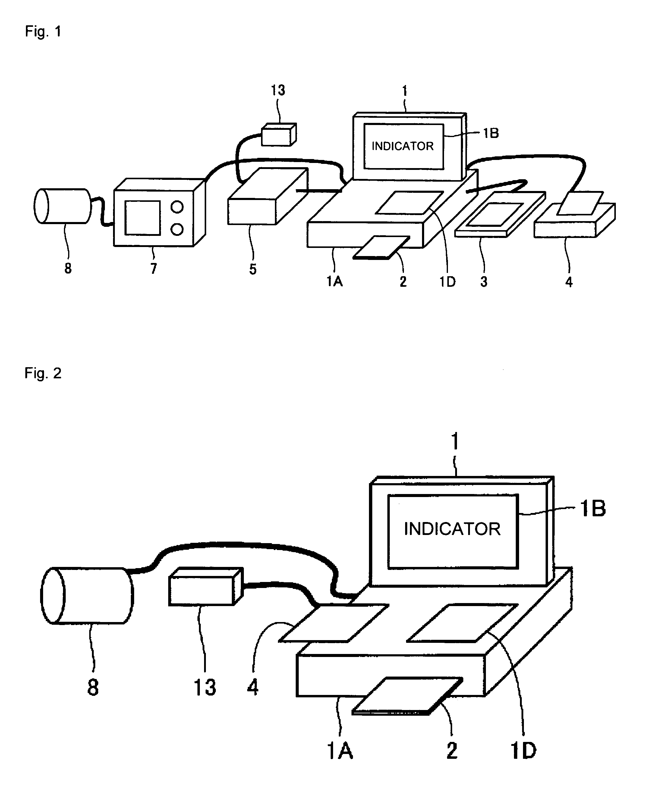
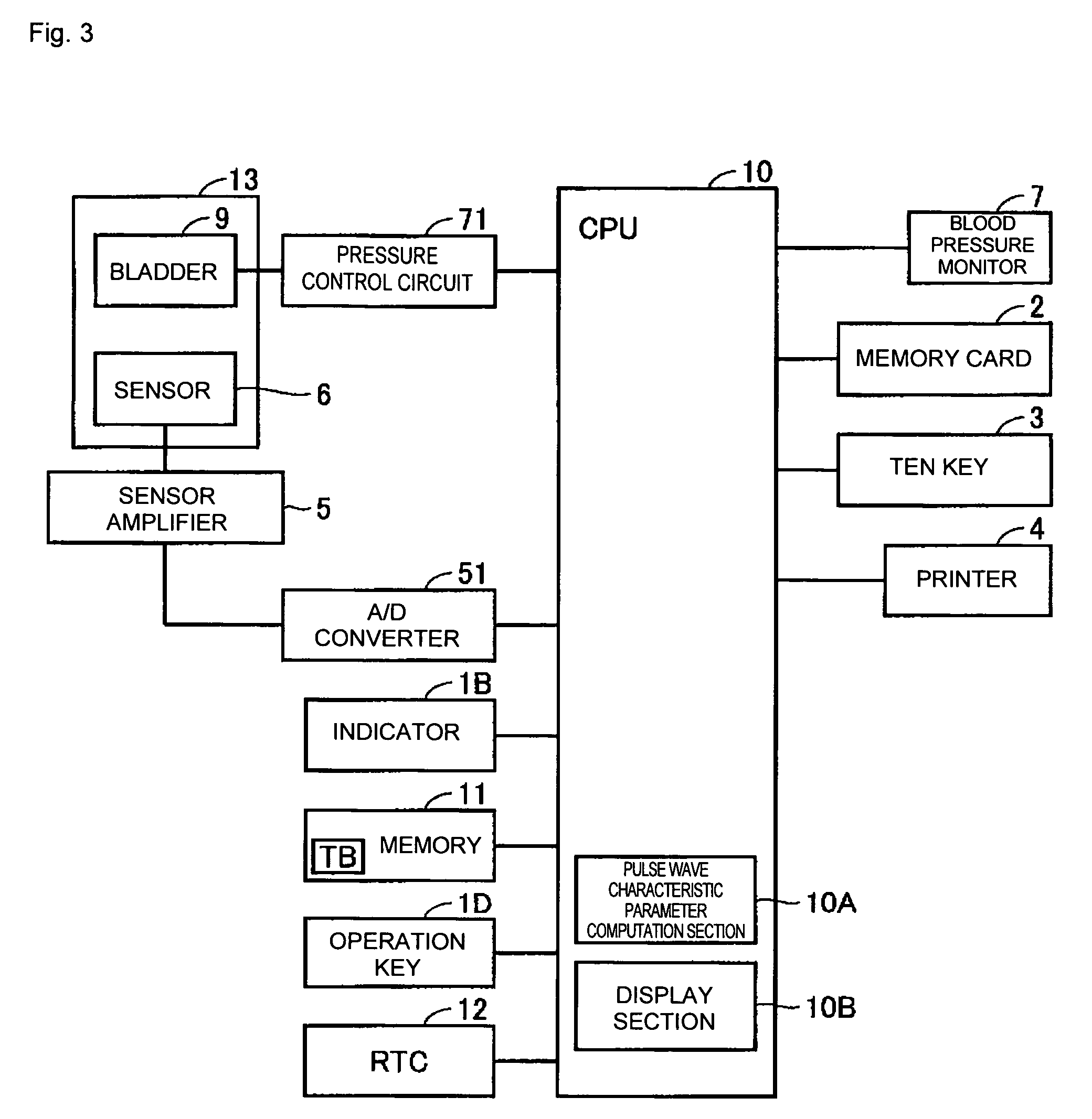
[0066]FIGS. 1 and 2 illustrate appearances of a pulse wave monitoring device for supporting a diagnosis according to an embodiment. FIG. 1 shows the appearance in the case where the device is separated into a plurality of units, and FIG. 2 shows the appearance in the case where the device includes the units. FIG. 3 illustrates a system constitution of the pulse wave monitoring device.

[0067]In FIGS. 1 to 3, the pulse wave monitoring device for supporting a diagnosis includes a PC (personal computer) 1, a memory card 2, a ten key 3, a printer 4, a sensor amplifier 5, a blood pressure monitor 7, a sensor unit 13, and an arm band 8. The PC 1 has a main body 1A, an indicator 1B and an operation key 1D for displaying various pieces of information on an external portion in an integral manner, and contains a CPU (central processing unit) 10, a memory 11 and a RTC (real time clock) 12....


PUM


Abstract

A sensor is pressurized adjustably against a patient's wrist and detects a pressurized pulse wave of a radial artery in a noninvasive manner so as to measure blood pressure on an arm band wound around the patient's predetermined portion. A CPU calculates indices reflecting a reflecting phenomenon of a pulse wave as organism information different from the blood pressure based on the detected pulse waveform, and relates the measured blood pressure value with calculated indices so as to display them on an indicator. A doctor checks displayed contents so as to clearly understand a state of a circulatory system represented by a correlation between the patient's blood pressure and the indices so as to be capable of obtaining information which supports a diagnosis and prescription quickly.

Description

BACKGROUND OF THE INVENTION[0001]1. Field of the Invention[0002]The present invention relates to a pulse wave monitoring device for monitoring a pulse wave of an organism and, more particularly, to a pulse wave monitoring device for supporting a diagnosis.[0003]2. Description of the Related Art[0004]In close examinations for diagnosing cardio vascular diseases such as hypertension, anbulatory blood pressure monitoring, echocardiography using an ultrasonic diagnostic unit, eyegrounds test, electrocardiography, exercise tolerance test, and the like are conducted. The blood pressure measurement is, however, conducted the most widely as the examinations including the close examinations to general diagnosis. This is because the blood pressure measurement has excellent characteristics such that it can be conducted simply in a noninvasive manner and a measuring device is more inexpensive than devices for another examinations.[0005]Since information obtained form the blood pressure measurem...

Claims


Application Information

Patent Timeline
Patent Type & Authority Patents(United States)
IPC IPC(8): A61B5/02A61B5/022A61B5/0245
CPCA61B5/02A61B5/02007A61B5/022A61B5/02108A61B5/7239A61B5/742
Inventor TANABE, KAZUHISAKITAWAKI, TOMOKIITONAGA, KAZUNOBUSATO, HIRONORIHASHIMOTO, MASAOMIYAWAKI, YOSHINORI
Owner OMRON HEALTHCARE CO LTD
Why Eureka
Try Eureka