Storage apparatus

a technology of storage apparatus and chamber, which is applied in the direction of biomass after-treatment, instruments, and analysis using chemical indicators, etc., can solve the problems of reducing the number of microplates, uneven gas flow inside the chamber, and ambient conditions differing from position to position within the chamber, etc., and achieves the effect of convenient manipulation

Active Publication Date: 2008-02-05
PHC HLDG CORP
View PDF16 Cites 61 Cited by
  • Summary
  • Abstract
  • Description
  • Claims
  • Application Information

AI Technical Summary

Benefits of technology

[0016]Another object of the present invention is to provide a storage apparatus comprising a container transport device which can be removed from the chamber without being disassembled, the chamber being simple in construction.
[0018]With the storage apparatus of the present invention, the motor of the transport device is disposed inside the chamber along with the main body portion of the device, without causing the output shaft of the motor to extend through the wall of the chamber. Accordingly, the device can be removed from the chamber almost without disassembling the device. The chamber need not be provided with a bearing for supporting the output shaft of the motor. This makes the chamber simpler than in the prior art.
[0024]Another object of the present invention is to provide a storage apparatus which is easy to manipulate by the operator.
[0028]With the storage apparatus of the present invention, the container can be automatically transported merely by depressing a start button without necessitating the manipulation by the operator to specify the accommodating portion wherein the container is to be accommodated or to input container identification information. The storage apparatus is therefore easy to manipulate by the operator.

Problems solved by technology

This entails the problem of reducing the number of microplates that can be accommodated in the chamber.
Thus, the gas discharge outlet is positioned at one side of the interior of the chamber, consequently producing a markedly uneven flow of gas inside the chamber and giving rise to the problem that the ambient conditions differ from position to position within the chamber.
Accordingly, for the maintenance of the transport device, it is necessary to remove the motor from the chamber and to disassemble the main body of the transport device within the chamber to some extent, hence the problem of necessitating a cumbersome procedure.
This results in the problem of making the chamber complex in construction.
Accordingly, if it is attempted to install microplate racks of different structure in order to accommodate microplates having a thickness larger than the predetermined pitch, there arises the problem the control program must be rewritten.
The incubator described therefore has the problem that the operator must perform a very cumbersome manipulation procedure.

Method used


Image

  • Storage apparatus
  • Storage apparatus
  • Storage apparatus

Examples


Embodiment Construction

Overall Construction

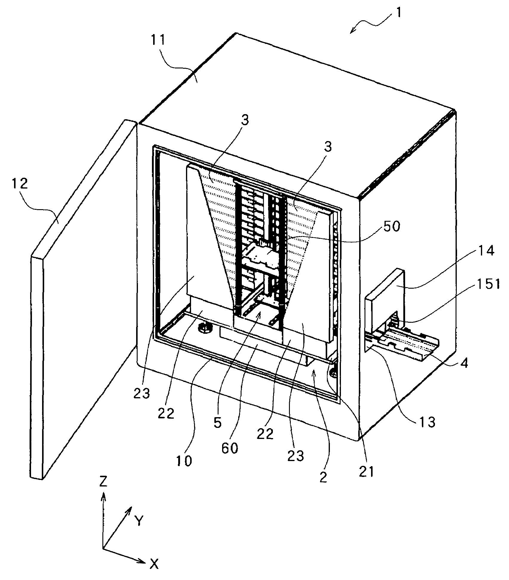
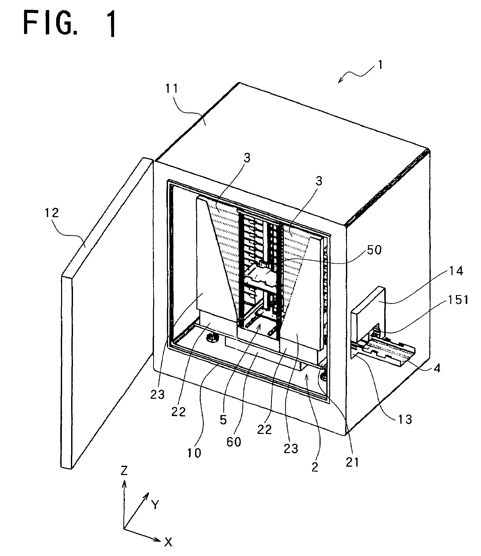
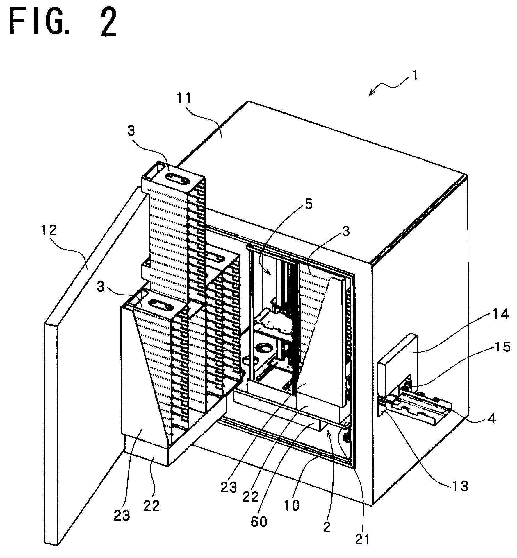
[0086]With reference to FIGS. 1 and 2, an incubator 1 embodying the present invention comprises a chamber 11 having a front opening 10 and a door 12 for closing the opening 10. An incubator unit 2 is accommodated in the interior of the chamber 11. A microplate inlet 13 is formed in a side wall of the chamber 11 and has a microplate carriage mechanism 4 attached thereto.

[0087]As shown in FIG. 3, the chamber 11 has in an inner portion thereof an environment adjusting device 6 for adjusting the temperature, humidity and the concentration of CO2 inside the chamber. The innermost wall of the chamber 11 has a discharge outlet 62 provided with a fan for forcing out a gas for adjusting the environment as specified by the device 6 toward the space in the center of the chamber. Attached to the inside wall of the chamber 11 are a thermometer 63, CO2 densitometer 64 and hygrometer 65 which constitute a sensor unit of the environment adjusting device 6. A camera 7 is installe...


PUM

PropertyMeasurementUnit
temperatureaaaaaaaaaa
sizeaaaaaaaaaa
delivery timeaaaaaaaaaa

Abstract

The invention provides an incubator 1 wherein a microplate transport device 5 is disposed inside a chamber 11 centrally thereof. The transport device 5 comprises a transport table 50 for placing a microplate thereon and is capable of driving the table 50 along the directions of three axes, i.e., X-axis, Y-axis and Z-axis. A plurality of stackers 3 are arranged in the direction of Y-axis at each of opposite sides of the transport device 5 along the direction of X-axis. Each of the stackers 3 has a plurality of microplate accommodating portions arranged in the direction of Z-axis. The microplate is movable into or out of the desired accommodating portion by the transport device 5.

Description

FIELD OF THE INVENTION[0001]The present invention relates to storage apparatuses for storing samples on microplates within a chamber which is adjusted to predetermined ambient conditions.BACKGROUND OF THE INVENTION[0002]FIG. 57 shows an incubator 9 conventionally used for cultivating various microorganisms or cells. The incubator 9 comprises a chamber 91 having an opening 90 closable with a door 92 and a plurality of racks 93 arranged in the interior of the chamber, and is adapted to place a plurality of microplates 31 on the respective racks 93. The chamber 91 is provided with an environment adjusting device (not shown) for adjusting the ambient conditions inside the chamber 91, such as temperature, humidity, carbon dioxide concentration, etc. Samples on the microplates 31 are cultivated under suitable ambient conditions set by the device.[0003]To check the state of samples being cultivated in the incubator 9, the microplate 31 is withdrawn from the chamber 91, and the samples are ...

Claims


Application Information

Patent Timeline
Patent Type & Authority Patents(United States)
IPC IPC(8): C12M1/00B65G1/00B65G65/00C12M1/34C12M3/00B01L1/00B01L99/00G01N35/02
CPCC12M23/48C12M41/14Y10S435/809
Inventor YOKOI, YASUHIKOHOUJOU, MIKIOYAMAMOTO, HIROSHIETOU, DAISUKE
Owner PHC HLDG CORP
Why Eureka
Try Eureka