
CDMA receiver

a receiver and code division technology, applied in the field of cdma receivers, can solve the problems of increasing complexity, cost and/or power use of receivers, and affecting the reception of cdma signals, and achieving the effects of increasing the complexity, cost and/or power use of receivers, and increasing the complexity of information spectrum

Inactive Publication Date: 2008-02-05
NOKIA MOBILE PHONES LTD
View PDF54 Cites 23 Cited by
  • Summary
  • Abstract
  • Description
  • Claims
  • Application Information

AI Technical Summary

Benefits of technology

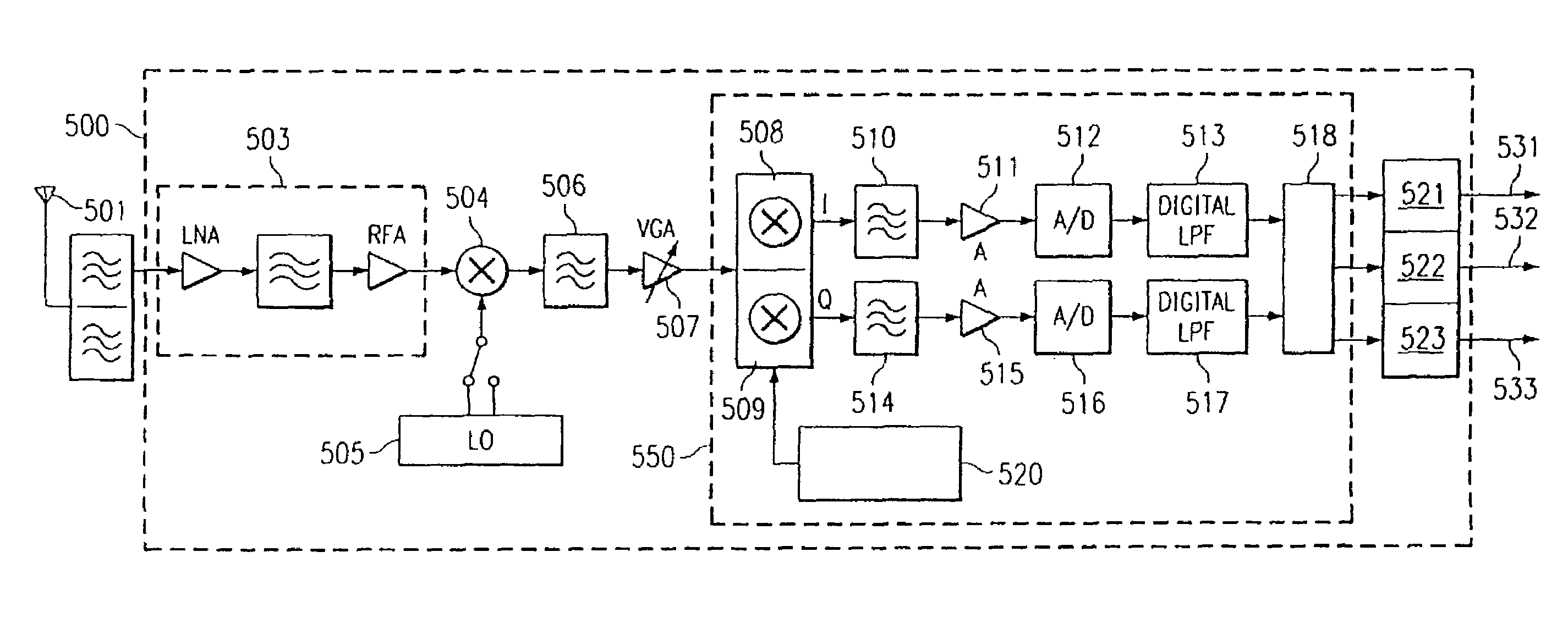
[0015]The present invention provides a method and apparatus for receiving multi-carrier CDMA signals that allows efficient implementation of a CDMA receiver in CDMA systems having multiple modes of operation. The invention utilizes multi-tone down conversion within a CDMA receiver operating in a multi-carrier mode.
[0016]Use of multi-tone down conversion in the receiver allows the number of components required to process a multi-carrier (MC) CDMA signal to be reduced and furthers efficient design of CDMA receivers operating in multiple modes, such as an MC-CDMA / CDMA receiver that may include, for example, a TIA / EIA cdma2000 first generation (cdma2000—1x) mode.
[0021]Implementations may include one or more of the following advantages. A receiver can operate to receive multiple signal types, such as IS-95, 3G—3x, and 3G—1x signals. A common set of intermediate frequency (IF) band pass filters (BPFs) and base-band (BB) low pass filters (LPFs) may be used for operation in different modes. This may reduce cost and part size compared with devices using different sets of intermediate filters and base band filters for different modes of operation.

Problems solved by technology

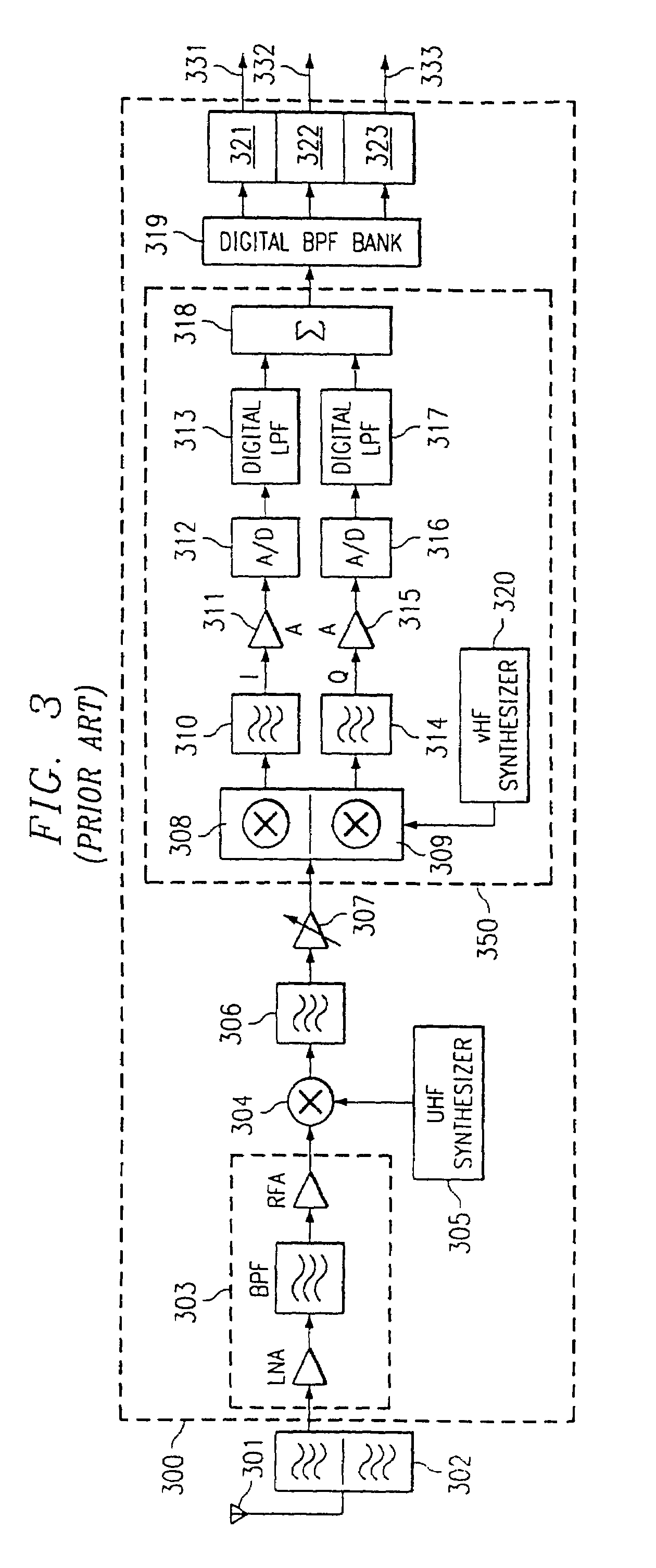
Frequency folding at down-converters 308 and 309 can result in the corruption of the information spectrum.
The use of multiple filter sets to receive different types of CDMA signals may increase the complexity, cost, and / or power use of the receiver 400 or may have other disadvantages.
As third-generation systems are implemented, initial coverage may be limited.
This additional circuitry may add additional size, cost, and complexity to the receiver.

Method used


Image

  • CDMA receiver
  • CDMA receiver
  • CDMA receiver

Examples


Embodiment Construction

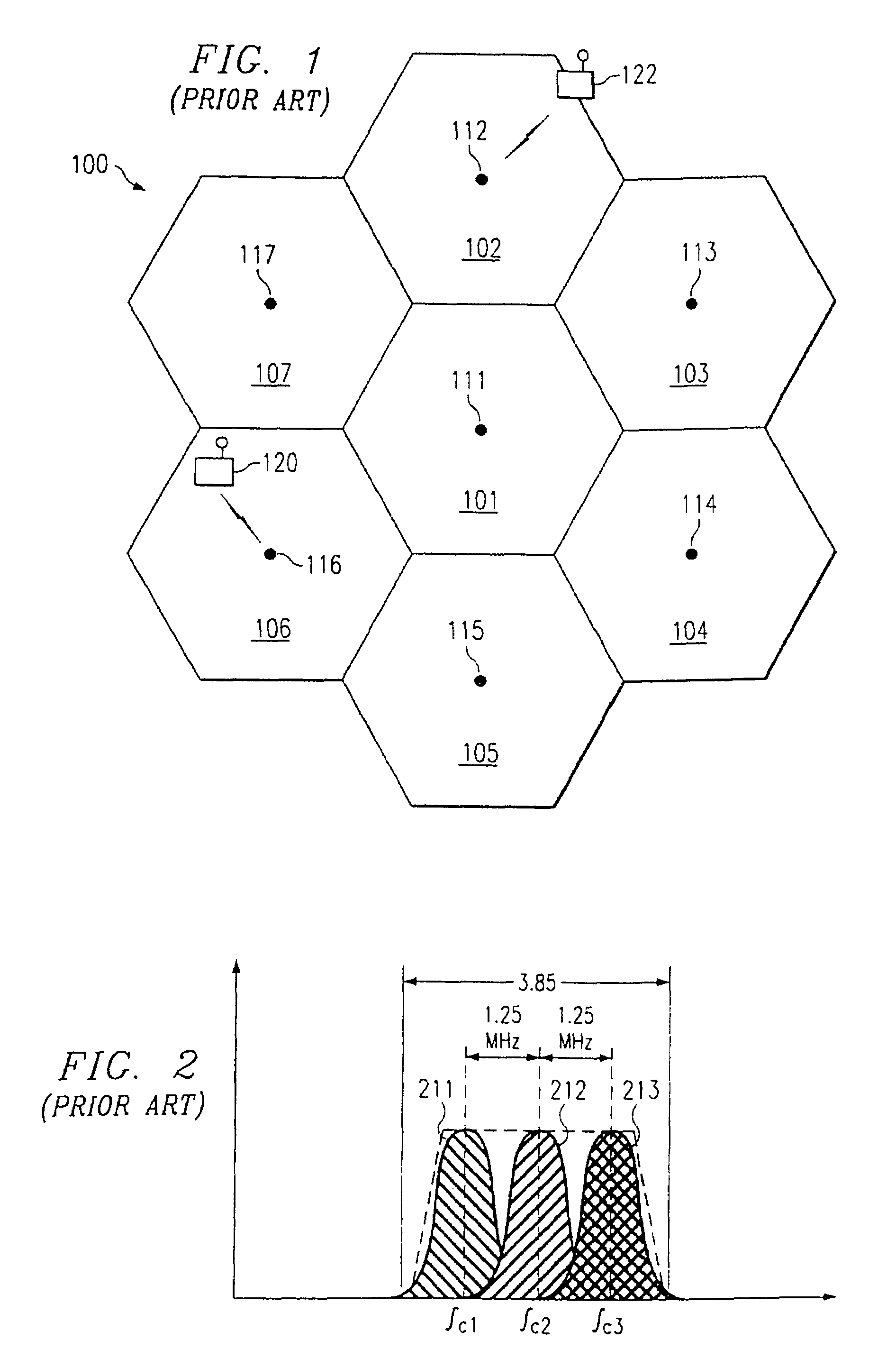
[0032]FIG. 5 is a block diagram of multimode receiver 500 according to an embodiment of the invention. Receiver 500 may support multiple operational modes (for example, MC-CDMA and IS-95 modes). Receiver 500 supports multimode operation using a unique down-conversion mechanism that allows a wide bandwidth signal to be filtered, amplified and / or otherwise processed using common circuitry compatible with both a wide and a narrower bandwidth signal. More particularly, the receiver 500 has a single carrier mode in which the receiver 500 receives and despreads a CDMA channel transmitted in a single RF band (such as an IS-95 signal), and a multi-carrier mode in which the receiver 500 simultaneously receives and despreads multiple CDMA channels from different RF bands (e.g., bands 211-213 of FIG. 2).

[0033]An exemplary IS-95 / MC-CDMA implementation is described to further explain the operation of the receiver 500. In the description that follows, IS-95 mode refers to a single-carrier mode in...


PUM


Abstract

A signal reception method including method and apparatus for receiving a signal, down converting the received signal through multi-tone down conversion to form an intermediate signal, and decoding the intermediate signal to extract data. In an embodiment, the received signal may include multiple transmission bands of a multi-code (MC)-CDMA signal, each of which occupies a different spectrum. Each of the transmission bands also includes an information channel signal. When the received MC-CDMA signal is down converted through multi-tone down conversion, the intermediate signal is formed. The intermediate signal includes a common spectrum that includes an information channel from a plurality of transmission bands. When the intermediate signal is decoded, data from a plurality of information channel bands is extracted. The method and apparatus may be implemented in a multi-mode MC-CDMA / CDMA receiver.

Description

FIELD OF THE INVENTION[0001]The present invention relates generally to code division multiple access (CDMA) receivers, and more particularly, to a method and apparatus for receiving multi-carrier (MC) CDMA signals that allows efficient implementation of a CDMA receiver in CDMA systems having multiple modes of operation.BACKGROUND OF THE INVENTION[0002]FIG. 1 shows a cellular system 100. The cellular system 100 coverage area may be divided into separate areas defined by cells 101-107. Each mobile station 120-122 may operate within the coverage area of cellular system 100. Each cell 101-107 is controlled by a radio frequency transmitting and receiving base station 111-117 that allows base station-to-mobile and reverse-link (mobile station to base station) channels to be established. The reverse-link and forward-link channels provide paths for communication between mobile stations and an associated base station 111-117. Cellular system 100 may be implemented according to one of the man...

Claims


Application Information

Patent Timeline
IPC IPC(8): H04K1/00H04L27/28H04L27/30H04B1/692H04B1/707H04L5/02
CPCH04B1/707H04L5/026H04B1/692H04B2201/70709
Inventor GU, QIZHENG
Owner NOKIA MOBILE PHONES LTD
Learn More