Lead placement device

a technology of implantable leads and leads, applied in the field of implantable medical devices, can solve the problems of affecting affecting the operation, and presenting the surgeon with certain difficulties, so as to facilitate the placement and attachment of the pacing and limit the torque availabl

Active Publication Date: 2008-02-05
PACESETTER INC
View PDF16 Cites 162 Cited by
  • Summary
  • Abstract
  • Description
  • Claims
  • Application Information

AI Technical Summary

Benefits of technology

[0012]The invention, then, is a two-piece steerable introducer that facilitates the placement and attachment of a pacing lead to the exterior of the heart. The exterior sheath provides the steering motion while the inner sheath holds the leads and allows the user to rotate the lead to attach a helical coil such as those found on most positive fixation leads. This is in contrast to current practice which uses a single steerable sheath using a stylet or other internal drivers that severely limit the torque available to fasten the lead.

Problems solved by technology

Both techniques involve a significant incision and the post-operative issues associated with large incisions, such as recuperation time, pain, risk of infection, and cosmetic results.
These disk-like suture pads may present the surgeon with certain difficulties during insertion via a typical thoracoscopy introducer.
Unless extreme caution is exercised, the lead may be damaged.
To avoid the potential for snagging the lead, surgeons may have to use a larger than necessary introducer, resulting in a larger incision, more scarring, and potentially more post-operative pain for the patient.
In addition, if a conventional suture pad epicardial lead must be relocated due to improper threshold or some other indication, the surgeon must expend time and effort cutting the existing sutures and sewing the pad to the new location.
The fabrication of this system requires a series of complex molding and machining steps, often under relatively tight tolerances.
This is in contrast to current practice which uses a single steerable sheath using a stylet or other internal drivers that severely limit the torque available to fasten the lead.

Method used


Image

  • Lead placement device
  • Lead placement device
  • Lead placement device

Examples


Embodiment Construction

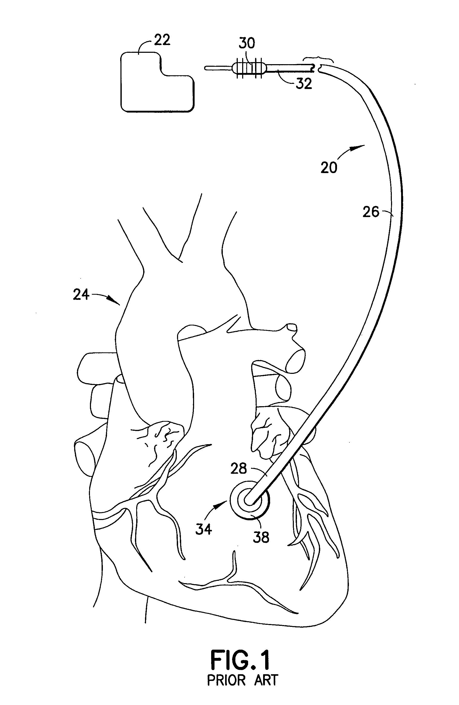
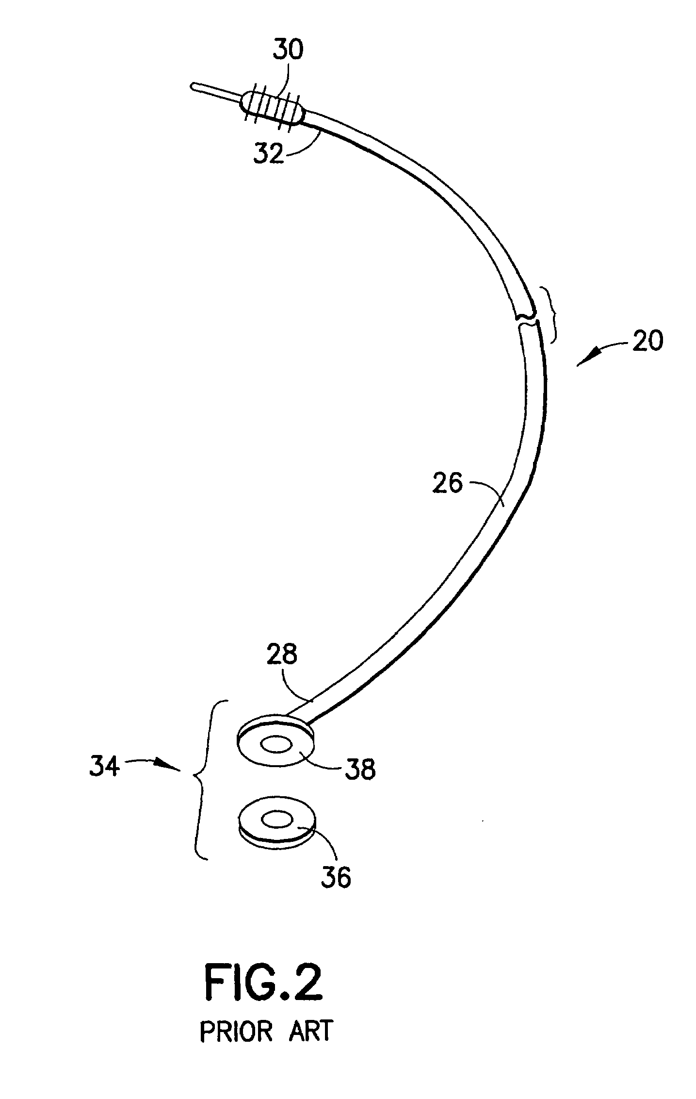
[0039]Refer now to the drawings and, initially, to FIGS. 1 and 2 in which are shown diagrammatic perspective views of a medical electrical, epicardial or myocardial lead 20 of a known design but which may be modified to incorporate features of the present invention for use in association with an electrical stimulator 22 such as a pacemaker or defibrillator providing electrical stimulation to a heart 24. Although the present invention will be described with reference to the embodiments shown in the drawings, it should be understood that the present invention can be embodied in many alternate forms or embodiments. In addition, any suitable size, shape or type of elements or materials could be used.

[0040]The lead 20 is adapted to conduct electrical stimulation from the electrical stimulator 22, which may be, alternatively and selectively, implantable or external to a site of the heart 24 and to conduct electrical signals of the heart from the site to the stimulator. The lead 20 include...


PUM


Abstract

Lead placement apparatus to transmit electrical signals to stimulate selected body tissue includes an introducer handle supporting a tubular outer sheath of flexible resilient material including a rigid section and a deflectable section adjacent the distal end, enabling the deflectable section to deflect among a plurality of positions in orientations transverse of a longitudinal axis. An operative member on the introducer handle connected to the distal end of the outer sheath serves to move that distal end. An inner tubular sheath of flexible resilient material slidably received within the outer sheath includes a driving socket fixed to its distal end whereby, with a lead slidably received within the inner tubular sheath and including a driven socket fixed to its distal end for releasable mating engagement by the driving socket, an electrode at the distal tip of the lead can be advanced and directed to the selected body tissue for stimulation.

Description

FIELD OF THE INVENTION[0001]The present invention relates generally to implantable medical devices for providing stimulating pulses to selected body tissue, and more particularly, to implantable cardiac stimulation leads of the epicardial type.BACKGROUND OF THE INVENTION[0002]Prior to the advent of endocardially implanted leads and associated surgical implantation techniques, surgeons and cardiologists traditionally relied on epicardial leads for cardiac stimulation and diagnosis. Median sternotomy or anterior thoracotomy were commonly used techniques to access the pericardium for epicardial lead implantation. Both techniques involve a significant incision and the post-operative issues associated with large incisions, such as recuperation time, pain, risk of infection, and cosmetic results.[0003]Patients and practitioners alike favor the use of endocardial leads for cardiac stimulation in most circumstances. The benefits of transvenous implantation are many, including improved post-...

Claims


Application Information

Patent Timeline
Patent Type & Authority Patents(United States)
IPC IPC(8): A61B19/00
CPCA61B19/22A61N1/0587A61B2019/2249A61B34/70A61B34/72
Inventor STEHR, RICHARD E.POTTER, DANIEL J.
Owner PACESETTER INC
Why Eureka
Try Eureka