
Integrated OTEC platform

a technology of otec and platform, applied in the direction of sustainable buildings, machines/engines, mechanical apparatus, etc., can solve the problems of complex structure, many details unanswered, and difficult construction, so as to simplify several requirements, simplify pumping requirements, and reduce the effect of pressure drop in the system

Inactive Publication Date: 2008-02-12
SAUCEDO EDUARDO
View PDF5 Cites 56 Cited by
  • Summary
  • Abstract
  • Description
  • Claims
  • Application Information

AI Technical Summary

Benefits of technology

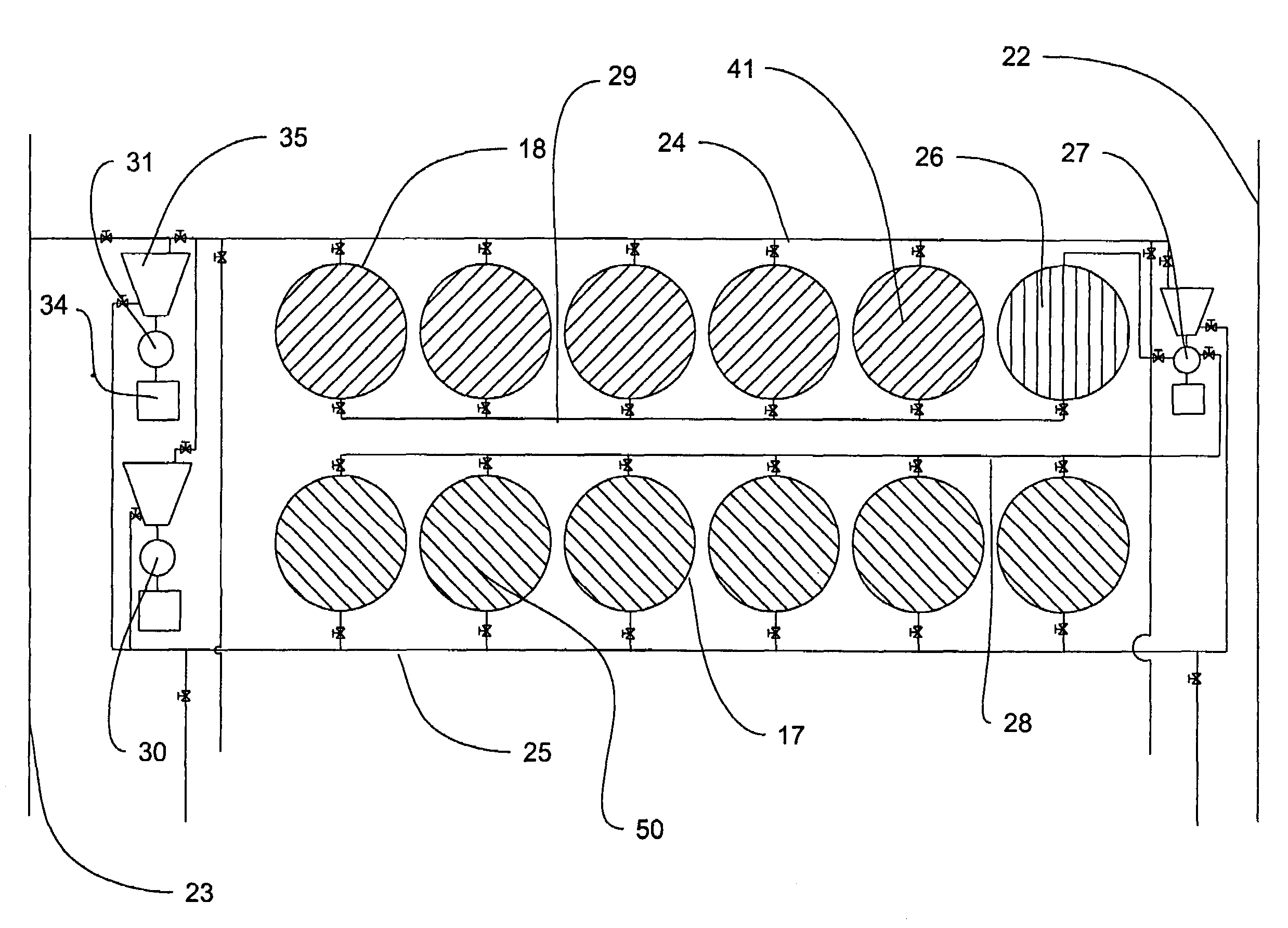
[0011]It is an object of the present invention to provide for an integrated platform for an OTEC plant that will simplify several requirements: (i) a way of receiving and distributing the cold water from the CWP to the condensers; (ii) a way of collecting and distributing the surface water to the evaporators; (iii) a way of collecting the spent cold and surface water and discharging it through a Discharge Water Pipe (herein called “DWP”); (iv) a way of integrating the heat exchangers with the distribution systems for cold and surface water utilizing vertical conduits as shells for the heat exchangers as described in patent application Ser. No. 11 / 119,882, and; (v) simplifying the pumping requirements.
[0012]It is a further object of the present invention to provide for simplified paths for both cold and surface waters, eliminate the need to pump above sea level and reduce the pressure drop in the system, reducing the parasitic losses of the overall system.
[0013]It is a further object of the present invention to provide an integrated platform to receive the cold water from the CWP into a cold water distribution tank, distribute the cold water through a plurality of conduits housing the condensers, with a plurality of collectors to receive the spent cold water below the sea surface, thus simplifying pumping requirements to discharge the spent cold water into a discharge tank connected to the DWP.
[0014]It is a further object of the present invention to provide an integrated platform with a plurality of surface water distribution conduits which will feed conduits housing the evaporators, with a plurality of collectors to receive the spent surface waters, also below sea level and discharging it to the same collector connected to the DWP.
[0015]It is a further object of the present invention to house the evaporators and condensers of the OTEC plant inside vertical conduits, simplifying the water piping arrangements, substantially reducing the pressure drop within the system and thus lowering the pumping requirements and improving the efficiency of an OTEC plant.
[0016]It is a further object of the present invention to provide for a plurality of pumps located on top of the collectors to pump the spent water into the DWP, allowing for the utilization of ready available large pumps, rather then designing and constructing very large pumps as suggested by the literature.

Problems solved by technology

The patent leaves many details unanswered that still needs substantial work.
Although the platform might be very stable, it is massive, weighing some 500,000 tons and the columns are cylindrical, 16 m in diameter and extending 75 m below the sea surface and would be difficult to construct since few shipyards might be able to provide such draft and would require offshore construction.

Method used


Image

  • Integrated OTEC platform
  • Integrated OTEC platform
  • Integrated OTEC platform

Examples


embodiment

Preferred Embodiment

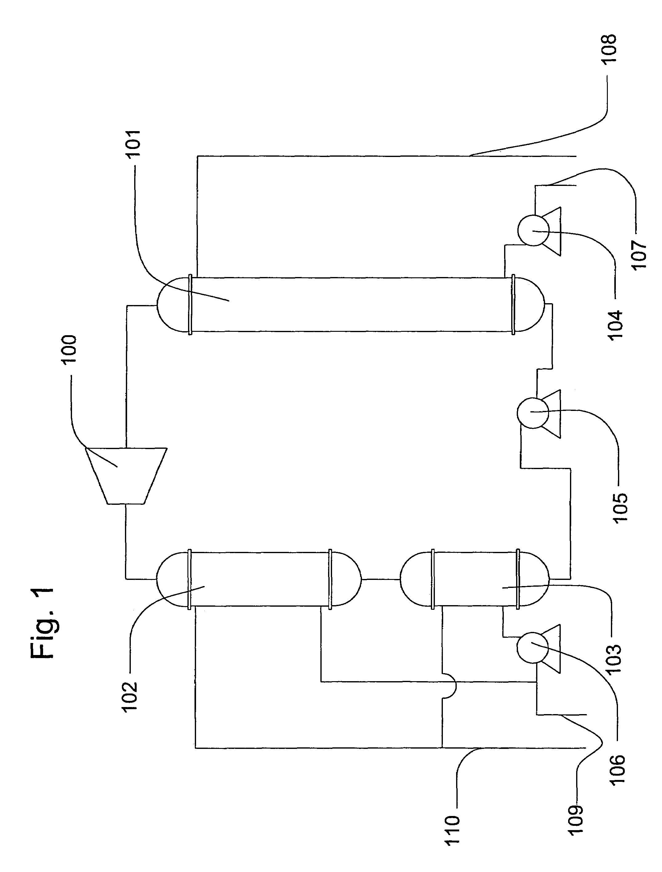
[0095]FIG. 1 illustrates a block diagram of a Closed Cycle OTEC plant. The process is rather simple. Cold water brought to the surface by the cold water inlet pipe 107 is injected by a cold water pump 104 into a condenser 101 where the working fluid is liquefied. The spent cold water is discharged by the cold water discharge pipe 108. By means of the working fluid pump 105 the condensed working fluid is fed first into the heater 103 and then into the evaporator 102 where the liquid working fluid is first heated and then is evaporated. The high pressure working fluid vapor produced by the evaporator enters into the turbo-generator 100 and the spent vapor is then fed into the condenser 101, closing the cycle. The surface water, fed by the surface water inlet pipe 109 is pumped into the heater 103 and evaporator 102 by the surface water pump 106 and discharged by the surface water discharge pipe 110. The simple block diagram masks many complexities of the practical ...


PUM


Abstract

An integrated platform to house an ocean thermal energy conversion (OTEC) system that utilizes: (i) a cold water circuit consisting of a way of receiving and distributing the cold water from the cold water pipe (CWP) to vertical conduits housing the condensers into collectors that discharge via large pumps into open discharge channels connected to the discharge water pipe (DWP); (ii) a surface water circuit consisting of a way of collecting and distributing the surface water to vertical conduits housing the evaporators to surface water collectors that discharge via large pumps into the same discharge channels connected to the DWP; (iii) means of adjusting the buoyancy of the integrated platform by adding water as ballast into floatation chambers in the hull surrounding the discharge channels or in a plurality of either vertical or horizontal flotation chambers to provide protection to the CWP and DWP and stability to the integrated platform. By adjusting the buoyancy of the platform such that the collectors are about level with the sea level, pumping requirements are minimized.

Description

CROSS-REFERENCE TO RELATED APPLICATIONS[0001]On Oct. 15, 2004, a Provisional Patent Application (PPA) was submitted. Confirmation number 3933 for Application No. 60 / 618,607 was mailed on Nov. 16, 2004. The following patent application refers to one of the inventions therein presented.[0002]In addition, this application incorporates application Ser. No. 11 / 079,200 dated Mar. 15, 2005, titled Modular Vertical Floating Pipe and application Ser. No. 11 / 119,882 dated May 3, 2005, titled Heat Exchangers with Plastic Tube Sheets.FEDERALLY SPONSORED RESEARCH[0003]Not ApplicableSEQUENCE LISTING OR PROGRAM[0004]Not ApplicableBACKGROUND OF THE INVENTION[0005]The present invention relates to the Ocean Thermal Energy Conversion (herein referred as “OTEC”) system and more particularly to a design of a platform for an OTEC plant that integrates the distribution and collecting systems for the cold and surface waters with the condensers and evaporators.[0006]OTEC systems are energy producing systems...

Claims


Application Information

Patent Timeline
Patent Type & Authority Patents(United States)
IPC IPC(8): F03G6/00
CPCB63B35/44F03G7/05B63B2035/4466Y02B10/20Y02E10/34Y02E10/46Y02E10/30
Inventor SAUCEDO, EDUARDO
Owner SAUCEDO EDUARDO
Learn More