
Cooling system for a marine propulsion device

a technology for propulsion devices and cooling systems, which is applied in the direction of machines/engines, vessel construction, lighting and heating equipment, etc., can solve the problems of affecting the operation of the vessel

Inactive Publication Date: 2008-02-12
BRUNSWICK CORPORATION
View PDF20 Cites 11 Cited by
  • Summary
  • Abstract
  • Description
  • Claims
  • Application Information

AI Technical Summary

Benefits of technology

[0026]In a particularly preferred embodiment of the present invention, the first coolant is water which is drawn from a body of water in which the marine propulsion device is operated, such as a lake or ocean, and the second coolant is ethylene glycol. The first cooling circuit is configured to prevent the circuit from being blocked by the residual quantity of water which can become solidified, such as by freezing, within the first cooling circuit after the marine vessel is removed from the body of water in which it has been operated. In certain embodiments of the present invention, the first cooling circuit is configured to prevent the first cooling circuit from being more than fifty percent blocked by the residual quantity of water which can become solidified. It should be understood that a partial blockage of the first cooling circuit might not cause damage to a marine propulsion device. In other words, a partial blockage might still allow sufficient water to flow past the occlusion and provide cooling for heat producing portions of the engine and associated peripheral components until the frozen occlusion has melted.
[0027]In a particularly preferred embodiment of the present invention, all portions of the first cooling circuit are configured to slope downwardly from the heat exchanger to the drive unit behind the transom of the marine vessel when a crankshaft of the engine is generally horizontal. In other words, with the marine vessel in its normal operating position, but out of the water, the downward slope of all portions of the first cooling circuit will facilitate the draining of water out of the cooling circuit and through an opening in the transom of the marine vessel. As such, a preferred embodiment of the present invention provides a first cooling circuit which is configured to prevent an occlusion, such as frozen water, from forming within any portion of the first cooling circuit when the marine vessel is removed from a body of water in which it has been operated.

Problems solved by technology

If residual cooling water freezes within the conduits of the cooling system, two potentially harmful events can occur.
First, the frozen cooling water can expand sufficiently to damage the conduit in which the residual water is trapped.
Secondly, frozen coolant can create an occlusion that is sufficiently large to block subsequent flow of fluids through a conduit.
This blockage of the cooling system can deprive heat generating portions of the system from cooling water and, as a result, those portions can overheat and be severely damaged.
Since cast iron tends to expand in volume as a result of corrosion of its surface areas, water outlet openings intended to perform a draining function can be partially or fully closed as a result of corrosion.

Method used


Image

  • Cooling system for a marine propulsion device
  • Cooling system for a marine propulsion device
  • Cooling system for a marine propulsion device

Examples


Embodiment Construction

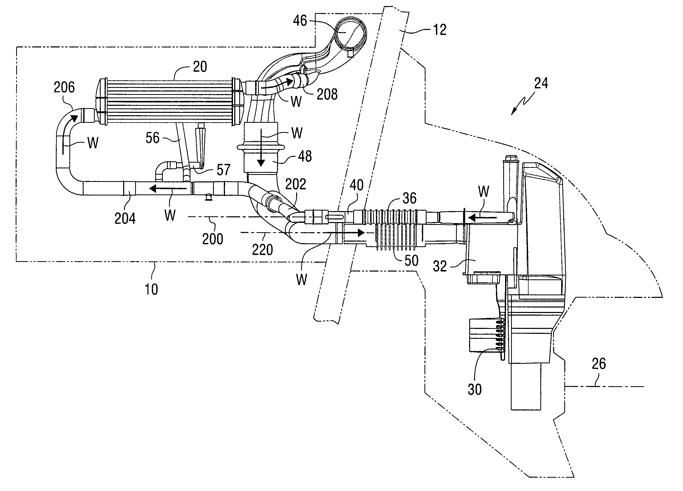
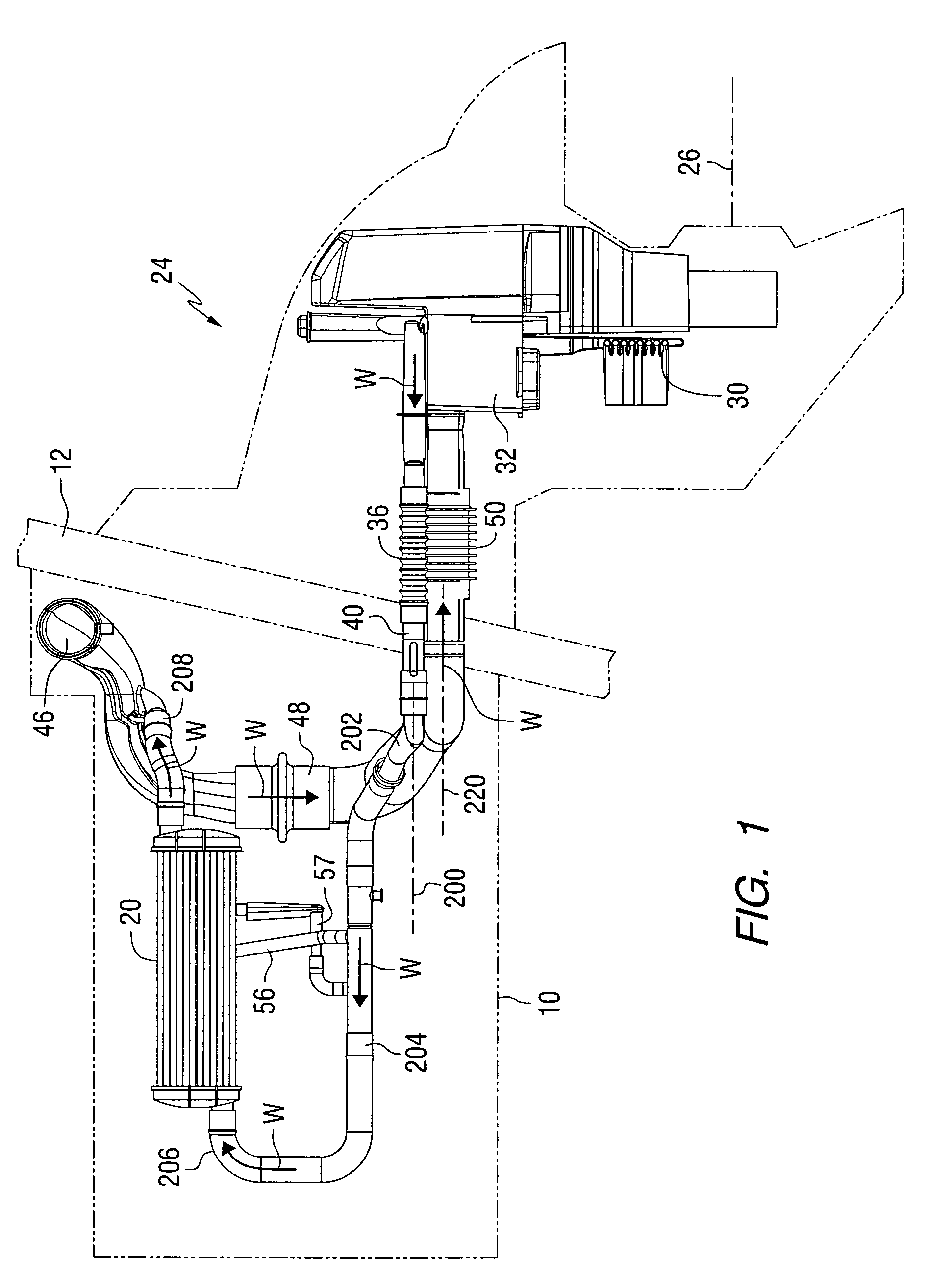
[0038]Throughout the description of the preferred embodiment of the present invention, like components will be identified by like reference numerals.

[0039]FIG. 1 is a side view which illustrates the relative positions of various components of a marine propulsion device. An engine 10 is schematically illustrated to show its relative position in front of a transom 12 of a marine vessel. The marine propulsion system illustrated in FIG. 1 could typically have first and second cooling circuits. Only the first cooling circuit is shown in FIG. 1. A second cooling circuit would provide for the circulation of a coolant, such as ethylene glycol, through cooling passages of the engine 10. The first cooling circuit, shown in FIG. 1, provides water from a body of water in which the marine vessel is operated. The first coolant circulated by the first cooling system is typically lake water or ocean water drawn from that body of water. The water circulated through the first coolant circuit passes t...


PUM


Abstract

A cooling system for a marine vessel is configured to allow all cooling water to flow out of the cooling circuit naturally and under the influence of gravity when the marine vessel is removed from the body of water. All conduits of the cooling circuit are sloped downwardly and rearwardly from within the marine vessel to an opening through its transom. Traps are avoided so that residual water is not retained within locations of the cooling system after the natural draining process is complete. The opening through the transom of the marine vessel is at or below all conduits of the cooling system in order to facilitate the natural draining of the cooling system under the influence of gravity and without the need for operator intervention.

Description

BACKGROUND OF THE INVENTION[0001]1. Field of the Invention[0002]The present invention is generally related to a cooling system for a marine propulsion device and, more particularly, to a cooling system that allows cooling water to drain automatically from the cooling system when a marine vessel is removed from the water in which it was operating and the crankshaft of an associated marine engine is generally horizontal.[0003]2. Description of the Related Art[0004]Many different types of drain and flush systems are known to those skilled in the art of marine propulsion devices. In environments where freezing temperatures can be experienced, it is occasionally necessary to remove cooling water from the cooling system of a marine vessel in order to prevent residual amounts of that water from freezing. If residual cooling water freezes within the conduits of the cooling system, two potentially harmful events can occur. First, the frozen cooling water can expand sufficiently to damage the...

Claims


Application Information

Patent Timeline
Patent Type & Authority Patents(United States)
IPC IPC(8): F01P3/20
CPCF01P3/207F01P11/20
Inventor CALDWELL, RODNEY M.JAEGER, MATTHEW W.SCHMIDT, KEITH W.
Owner BRUNSWICK CORPORATION
Learn More