
Near-field optical transducers for thermal assisted magnetic and optical data storage

a technology of optical transducers and thermal assisted magnetic and optical data storage, applied in the field of optical transducers, can solve the problems of not delivering a reasonable amount of optical power to the storage medium, devices useless for hamr recording, and still about two orders of magnitude too small for hamr

Active Publication Date: 2008-02-12
SEAGATE TECH LLC
View PDF25 Cites 247 Cited by
  • Summary
  • Abstract
  • Description
  • Claims
  • Application Information

AI Technical Summary

Benefits of technology

"The patent describes an optical transducer that can convert electromagnetic waves into surface plasms, which can be used for optical recording. The transducer includes a metallic nano-structure and a cladding material with a different refractive index. The technical effect of this invention is to improve the efficiency and accuracy of optical recording."

Problems solved by technology

Some prior systems have confined the light to a small spot but did not deliver a reasonable amount of optical power to the storage medium.
For all these approaches, confinement of the light depends on an aperture which is fabricated at the end of the structure and gives this kind of transducer the name “aperture probes.” Generally these devices suffer from very low light transmission rendering the devices useless for HAMR recording.
Although this is the state of the art, it is still about two orders of magnitude too small for HAMR.
Although doing so does increase the throughput to some extent, the most promising SP approach is still very inefficient due to a lack of an efficient SP launching technique.
In addition, all aperture probes suffer from a lower limit on spot size which is twice the skin depth of the metal film used to form the aperture.

Method used


Image

  • Near-field optical transducers for thermal assisted magnetic and optical data storage
  • Near-field optical transducers for thermal assisted magnetic and optical data storage
  • Near-field optical transducers for thermal assisted magnetic and optical data storage

Examples


Embodiment Construction

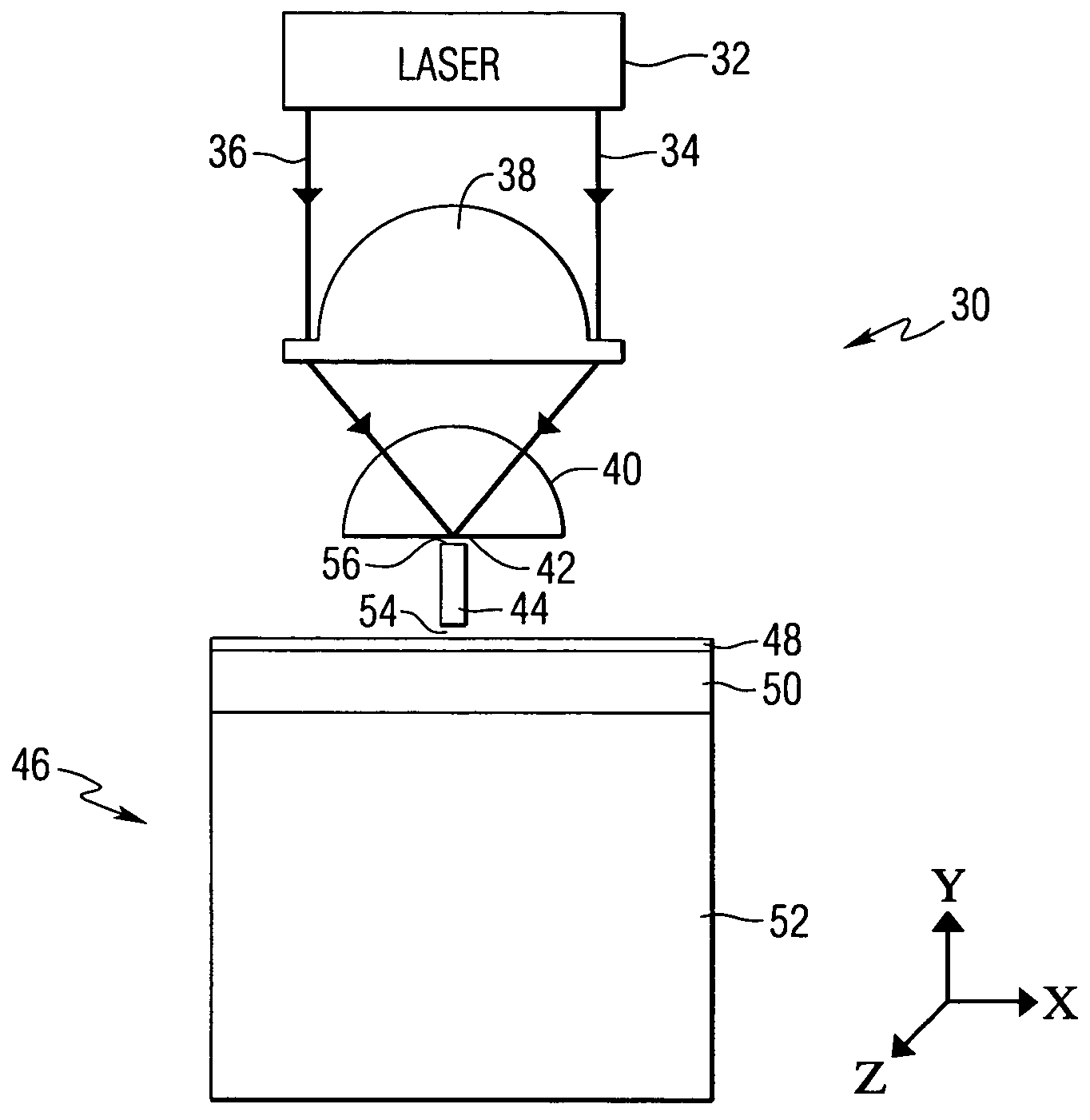
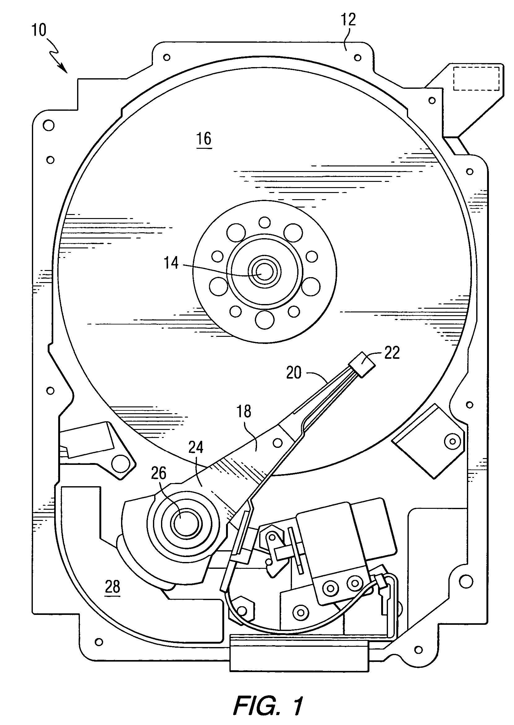
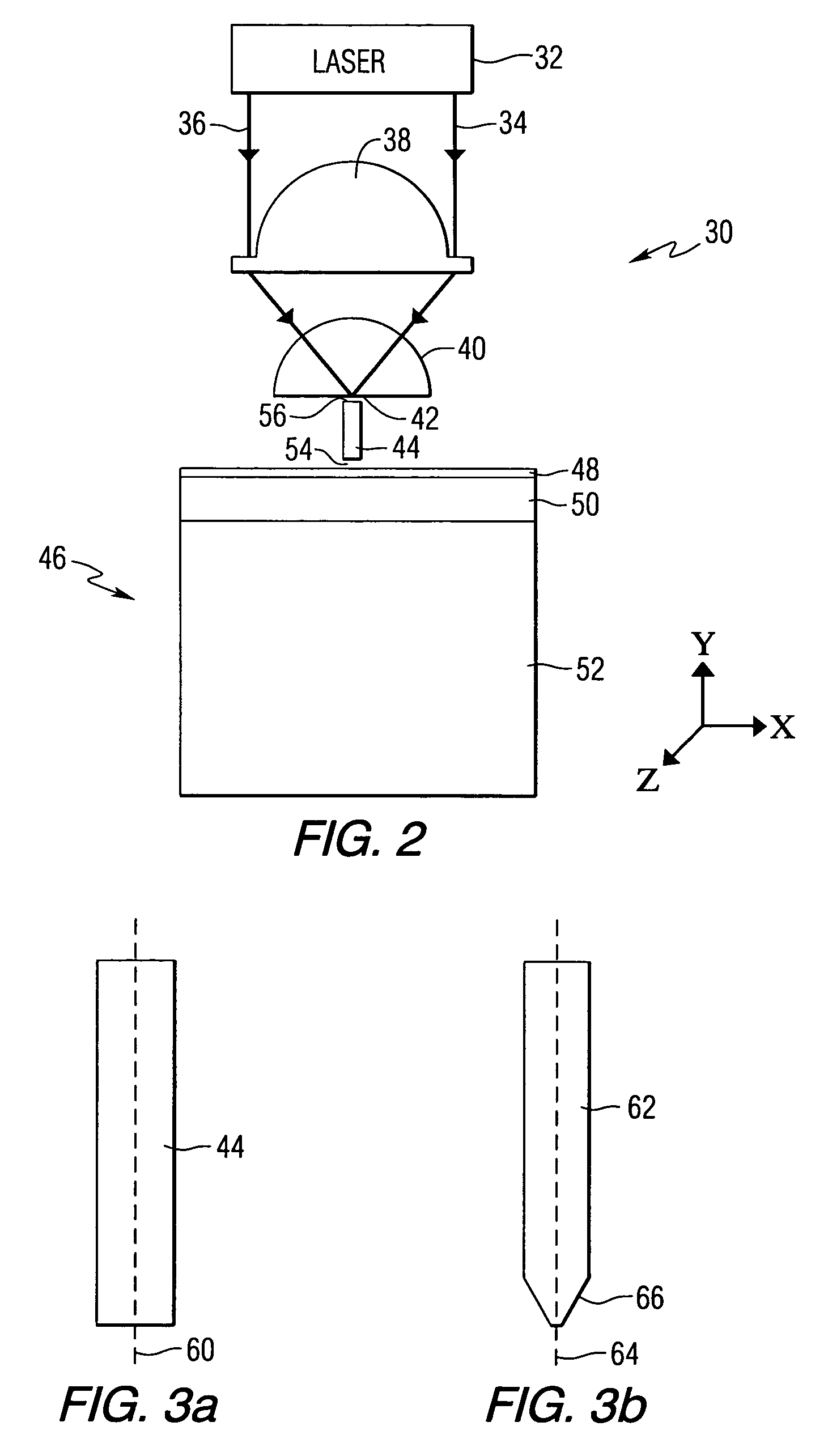
[0034]This invention encompasses transducers that can be used in magnetic and optical recording heads for use with magnetic and / or optical recording media, as well as magnetic and / or optical recording heads that include such devices and disc drives that include the recording heads. FIG. 1 is a pictorial representation of a disc drive 10 that can utilize recording heads constructed in accordance with this invention. The disc drive includes a housing 12 (with the upper portion removed and the lower portion visible in this view) sized and configured to contain the various components of the disc drive. The disc drive includes a spindle motor 14 for rotating at least one data storage medium 16 within the housing, in this case a magnetic disc. At least one arm 18 is contained within the housing 12, with each arm 18 having a first end 20 with a recording and / or reading head or slider 22, and a second end 24 pivotally mounted on a shaft by a bearing 26. An actuator motor 28 is located at th...


PUM

PropertyMeasurementUnit
widthaaaaaaaaaa
skin depthaaaaaaaaaa
thickaaaaaaaaaa

Abstract

An optical transducer comprises an optical element for directing an electromagnetic wave to a focal region and a metallic nano-structure having a longitudinal axis substantially parallel to an electric field of the electromagnetic wave, the metallic nano-structure being positioned outside of the optical element, wherein the electromagnetic wave produces surface plasmons on the metallic nano-structure. A cladding material having a refractive index differing from the refractive index of the optical element can be positioned adjacent to a surface of the metallic nano-structure. Magneto-optical recording heads that include the transducers and disc drives that include the magneto-optical recording heads are also included.

Description

STATEMENT REGARDING FEDERALLY SPONSORED RESEARCH OR DEVELOPMENT[0001]This invention was made with United States Government support under Agreement No. 70NANB1H3056 awarded by the National Institute of Standards and Technology (NIST). The United States Government has certain rights in the invention.FIELD OF THE INVENTION[0002]This invention relates to optical transducers, and more particularly to optical transducers that can be used in optical recording and thermally assisted magnetic recording.BACKGROUND OF THE INVENTION[0003]In thermally assisted optical / magnetic data storage, information bits are recorded on a layer of a storage medium at elevated temperatures, and the heated area in the storage medium determines the data bit dimension. In one approach, an electromagnetic wave in the form of light is used to heat the storage medium. To achieve high areal data density, it is preferred to have a high light throughput to an optical spot well below the diffraction limit to heat the st...

Claims


Application Information

Patent Timeline
Patent Type & Authority Patents(United States)
IPC IPC(8): G11B11/00G11B11/10G11B5/00G11B5/02G11B5/127
CPCG11B5/00G11B5/127G11B7/1387G11B11/10534G11B2005/0002G11B2005/0005G11B2005/0021G11B5/314G11B5/6088
Inventor PENG, CHUBINGCHALLENER, WILLIAM ALBERTSENDUR, IBRAHIM KURSAT
Owner SEAGATE TECH LLC
Learn More