Living body photometric device

a photometric device and living body technology, applied in the field of living body photometric devices, can solve problems such as difficulty in easily grasping a specific active region, and achieve the effect of accurately identifying an active portion of the brain and effectively comparing

Inactive Publication Date: 2008-02-12
HITACHI MEDICAL CORP +1
View PDF12 Cites 4 Cited by
  • Summary
  • Abstract
  • Description
  • Claims
  • Application Information

AI Technical Summary

Benefits of technology

[0011]In order to achieve the above object, the present invention is characterized in that a signal processing portion of the living body photometric apparatus is added of a function, which performs a principal component analysis for signals measured. The principal component analysis function is understood to be able to extract from the signals measured only signals corresponding to the loaded task. Thereby, an apparatus, which permits to effectively compare interregional signal intensity and to accurately identify an active portion in the brain in a clinical examination application such as the language area region identification.
[0014]According to the living body photometric apparatus of the present invention, since the representative signal reflecting most of the living body reaction when the task is given can be extracted as the task related signal, through comparison of the weight of the task related signal for every measurement channel, namely comparison of abundance frequency, an active portion which reacts most with respect to the task (language area when the task is language stimulus) can be accurately specified.
[0015]The present invention further provides a living body photometric apparatus with an improved display function. Namely, the living body photometric apparatus according to the present invention is characterized in that the input and output portion is adapted to display a waveform of the representative signal calculated through the principal component analysis in the signal processing portion and the weight of the representative signal for every measurement channel. Further, the living body photometric apparatus according to the present invention is characterized in that the calculated result of the correlation between the representative signal and the referential response signal is displayed together with the waveform of the representative signal.
[0017]In a further preferable living body photometric apparatus according to the present invention, the signal processing portion receives a condition for the task from the input and output portion and prepares a referential response signal depending on the condition. According to the present living body photometric apparatus, since a referential response signal of a suitable reaction pattern depending on the task can be used, correctness when extracting the task related signal is improved.

Problems solved by technology

Further, with the conventional display method in the living body photometric apparatus such as the time course representation of hemoglobin variation signals for every measurement channel and the topography representation, it was sometimes difficult to easily grasp a specific active region.

Method used


Image

  • Living body photometric device
  • Living body photometric device
  • Living body photometric device

Examples


Embodiment Construction

[0027]Herein below an embodiment of the present invention will be explained in detail. In the explanation below, as an object of light measurement, amount of hemoglobin (including oxy hemoglobin, deoxy hemoglobin and total hemoglobin) in a living body is referred to, however, in the living body photometric apparatus according to the present invention, substances such as cytochrome other that the hemoglobin which absorb light beams of near infrared region can be used as the measurement object.

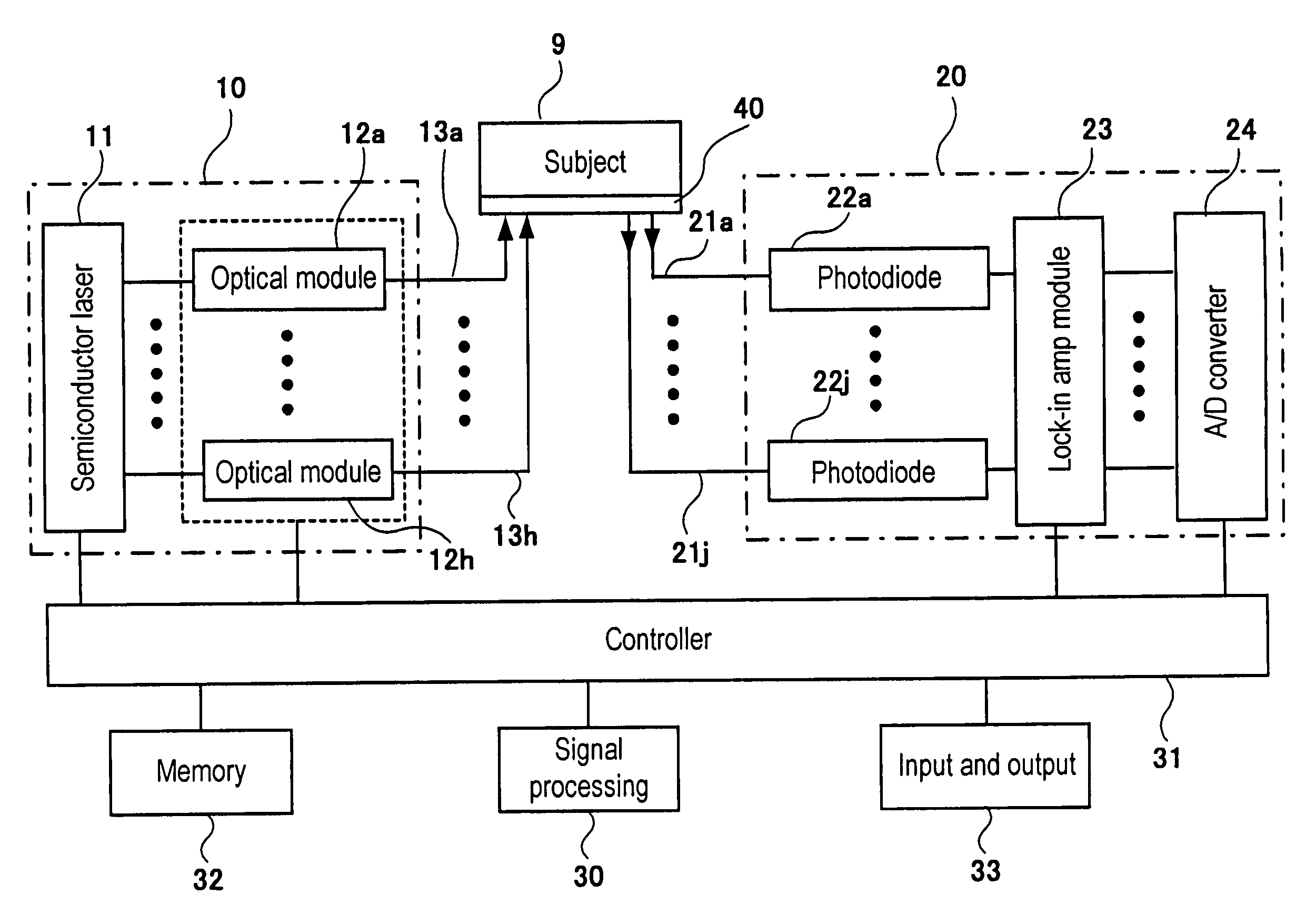
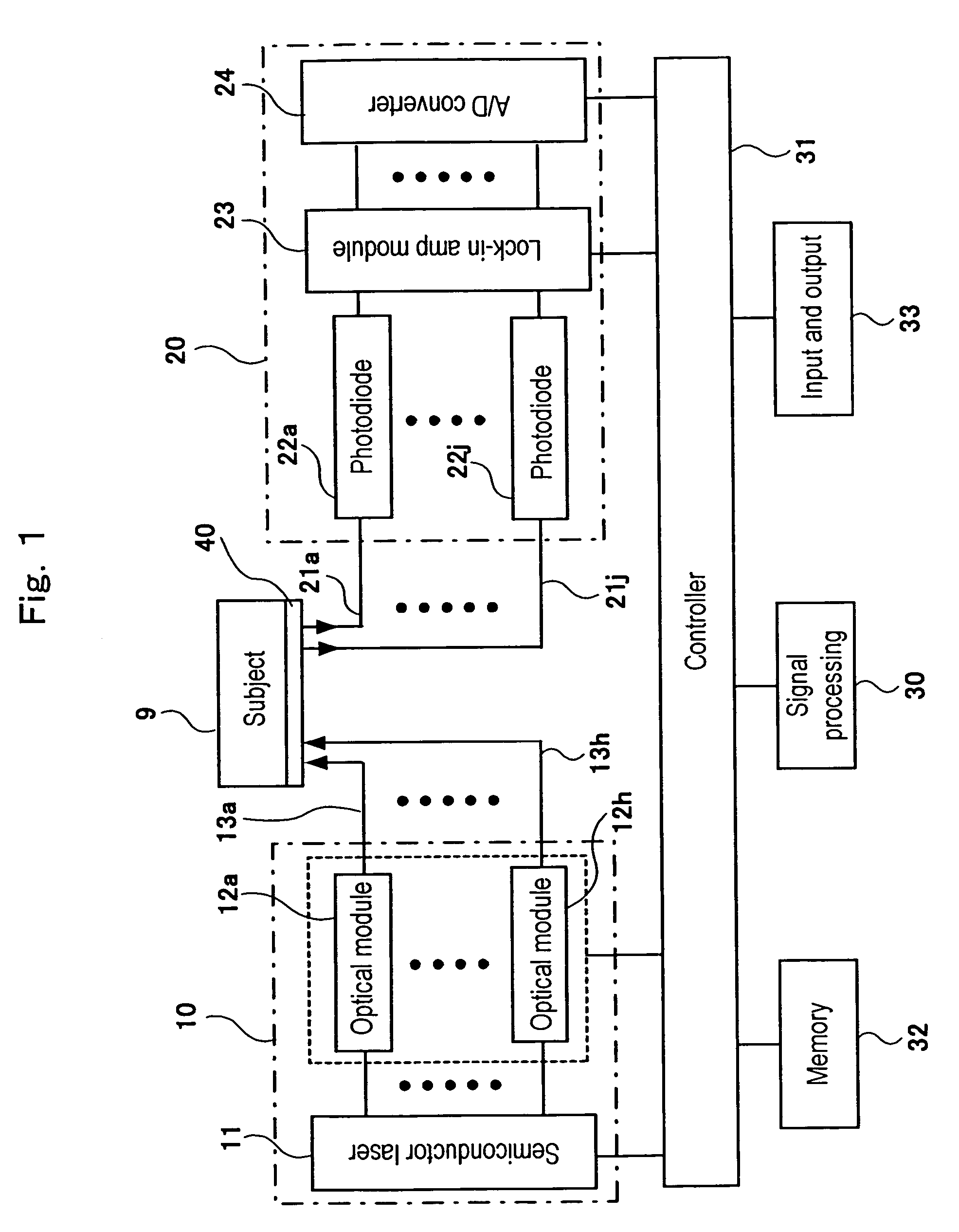
[0028]FIG. 1 is a block diagram showing a schematic entire structure of a living body photometric apparatus according to the present invention. The living body photometric apparatus is provided with a light source 10 which irradiates near infrared light beams to a living body, an optical measurement portion 20 which measures light passed through the living body and converts the same into an electrical signal and a signal processing portion 30 which calculates living body information, more specif...


PUM


Abstract

By making use of a set of loading of stimulation and no loading, variation signals in time of hemoglobin density at a plurality of measurement points of a subject attached of an optical measurement probe and corresponding to a plurality of channels are detected, and for the respective detected hemoglobin variation signals principal component analysis is performed as well as a representative signal having a higher contribution rate is extracted and the extracted representative signal is displayed on a monitor. A correlation between the representative signal and a task reference and response waveform representing a response pattern of a living body in response to a stimulation task is calculated, and a representative signal having the highest correlation value as calculated is displayed in a discriminable manner from the other signals as a task related signal which responds most to the stimulation given to the subject. From weights of the respective channels for the representative signal displayed as the task related signal, an optical measurement point or region, which responds most to the task is identified and displayed in discriminable manner.

Description

FIELD OF THE INVENTION[0001]The present invention relates to a living body photometric apparatus, which measures information inside a living body by making use of light beams and more specifically, relates to a living body photometric apparatus, which can specify accurately and easily a reactive portion inside the living body when a task load is given to the living body.CONVENTIONAL ART[0002]A living body photometric apparatus is an apparatus in which light beams having wavelength from visible region to infrared region are irradiated to a living body and reflected or scattered light beams inside the living body are detected so as to measure information inside the living body, and with which blood circulation and blood circulation dynamics inside the living body, moreover, variation in time of light absorption materials in blood such as hemoglobin can be easily measured with less restriction to a subject and without giving any harms to the subject. Thus clinical application of the li...

Claims


Application Information

Patent Timeline
Patent Type & Authority Patents(United States)
IPC IPC(8): A61B5/00
CPCA61B5/1455
Inventor KAWASAKI, SHINGOTANAKA, NAOKI
Owner HITACHI MEDICAL CORP
Why Eureka
Try Eureka