
Method and apparatus for dry forming of a fabric

a fabric and fabric technology, applied in the field of dry forming, can solve the problems of difficult to establish vacuum in an area between two, reduce the efficiency of the apparatus, and attach the pattern and/or the underside, and achieve the effect of high production speed, and large thickness of the fabri

Inactive Publication Date: 2008-02-19
DAN WEB HLDG AS
View PDF19 Cites 11 Cited by
  • Summary
  • Abstract
  • Description
  • Claims
  • Application Information

AI Technical Summary

Benefits of technology

"The present invention relates to a method and apparatus for producing non-woven fabrics with improved bonding and high production speeds. The method involves forming a first non-woven fabric on a first forming wire, transferring it to a second wire using a transfer wire, and optionally using an embosser to create a second non-woven fabric on the second wire. The non-woven fabrics are then transferred to a third wire for further processing. The apparatus includes a transfer wire and a vacuum box. The technical effects of this invention include improved bonding of non-woven fabrics, high production speeds, and the ability to produce multilayered fabrics with large thickness."

Problems solved by technology

When making an integrated product formed of several non-woven fabrics with large layer thickness, an attachment problem will arise from the vacuum box disposed under a former wire.
This entails a reduced efficiency for the apparatus.
However, it is difficult to establish vacuum in an area between two cards, and this means that it may be difficult to gent an airlaid gauze layer placed between two cards in an existing apparatus.

Method used


Image

  • Method and apparatus for dry forming of a fabric
  • Method and apparatus for dry forming of a fabric
  • Method and apparatus for dry forming of a fabric

Examples


first embodiment

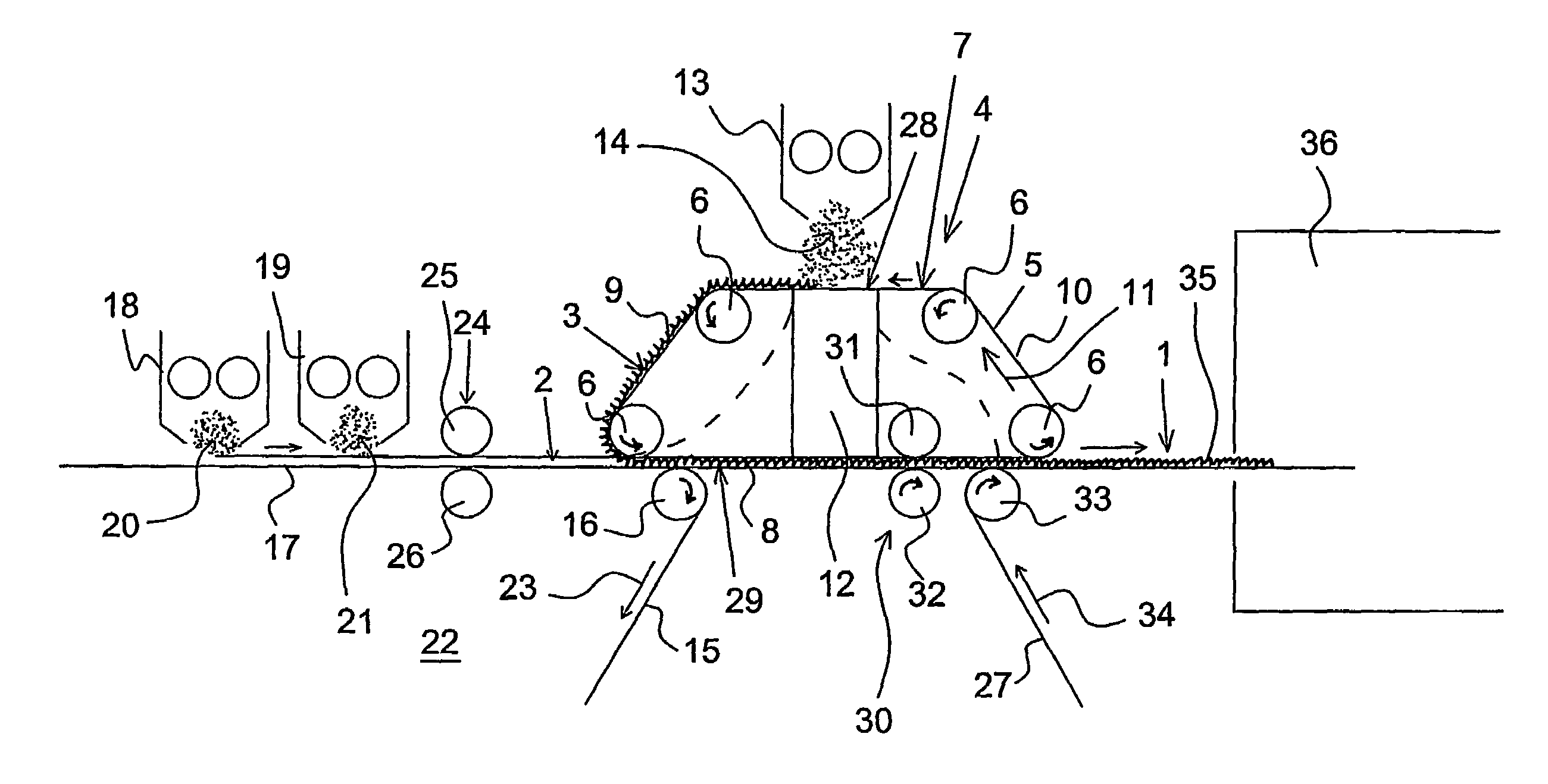
[0038]the apparatus as illustrated in FIG. 1 may e.g. be used with fibres which can contain binder fibres, e.g. polyester fibres, bicomponent fibres, or other binder fibres. By passing through the oven 36 fixation of the fabric 1 is thus provided.

second embodiment

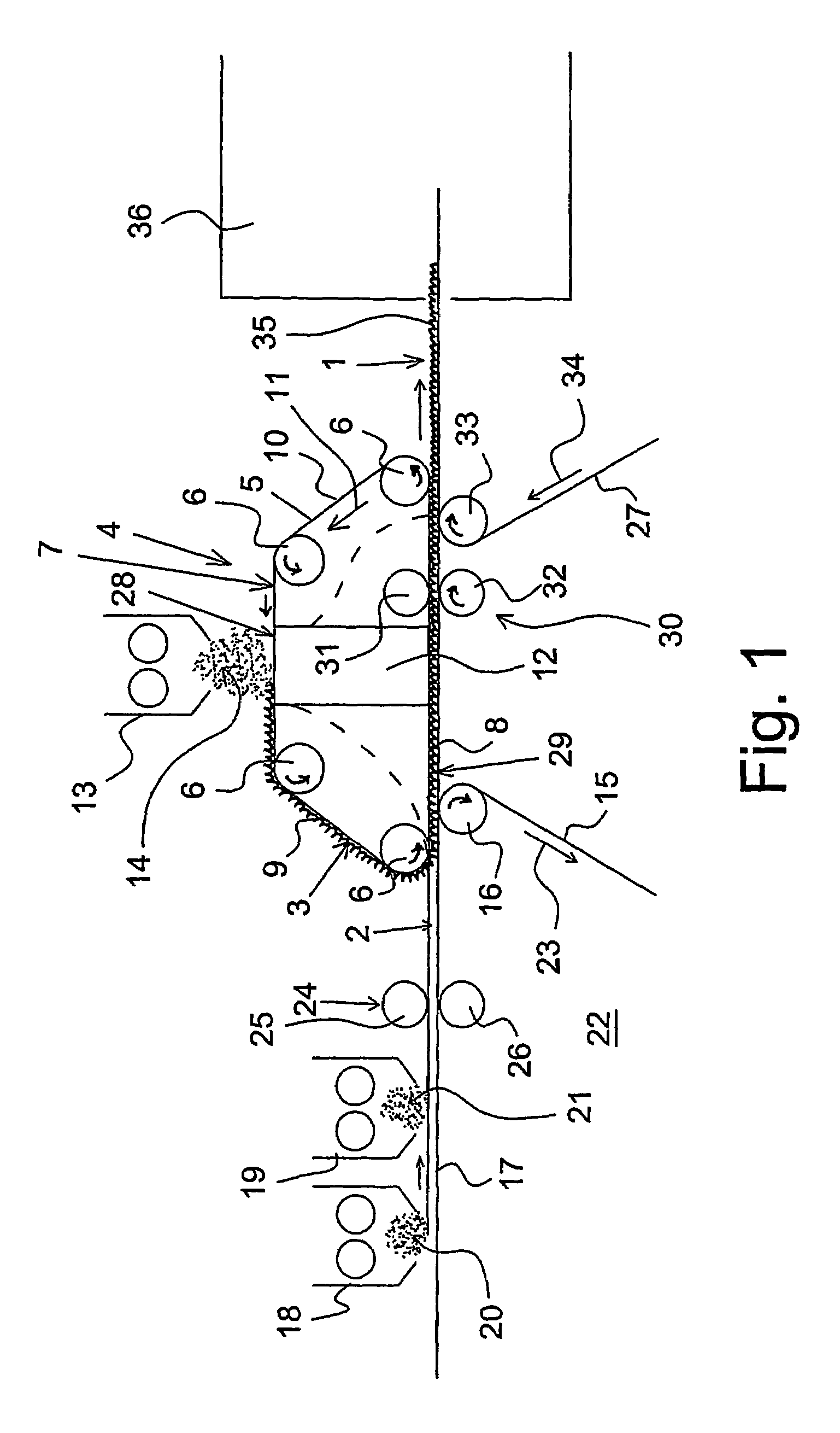
[0039]In FIG. 2 is illustrated the apparatus according to the invention. In this embodiment, the transfer unit 4 is used for formation of the second non-woven fabric 3 and for transferring the first non-woven fabric 2 which is formed on the forming wire 15 disposed upstream. The conveying wire 27 in the shown embodiment moves the fabric formed of the first and second non-woven fabrics 2, 3 to a further treating unit 37. In the shown embodiment, the treating unit is an arrangement for applying latex 38 which is sprayed on the fabric 1 using nozzles 39. After applying latex, the fabric is moved according to the arrow 40 to a further treating unit which e.g. can be an oven.

third embodiment

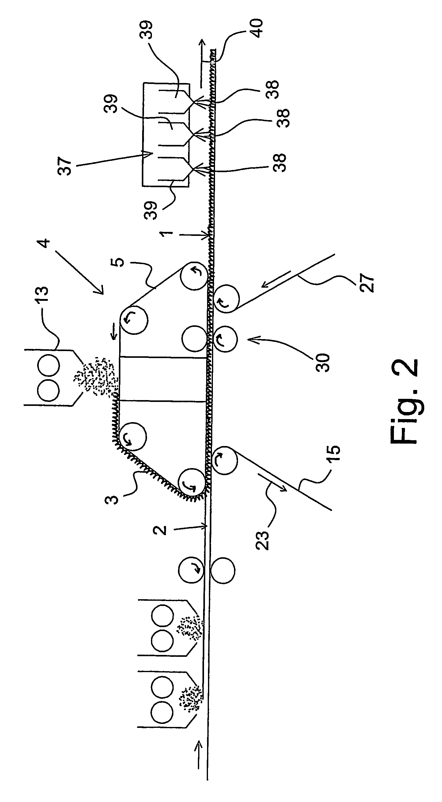
[0040]FIG. 3 also includes the transfer unit 4 over which the forming head 13 is disposed for forming the second non-woven fabric 3. In the third embodiment is also formed a first non-woven fabric 2 on the forming wire 15 which is disposed upstream in relation to the transfer unit 4.

[0041]In this third embodiment of the apparatus, the fabric is conveyed on the top side of the conveying wire 27 to a treatment unit 41. The treatment unit 41 is a hydroentanglement unit which fixes the fabric. It is constituted by a principle known per se, embodying a row of water jet nozzles 42, which are disposed above the upper run 35 of the conveying wire 27, providing downwards directed water jets 43. Below the upper run 37 of the conveying wire, other water jet nozzles 44 are provided that each forms an upwards directed water jet 45. The hydroentanglement unit 41 is shown schematically and will in practice look otherwise, but it is arranged so that fixation of the fabric 1 is achieved by a hydroen...


PUM

PropertyMeasurementUnit
densityaaaaaaaaaa
densityaaaaaaaaaa
densityaaaaaaaaaa

Abstract

A method and apparatus is described for use in dry forming a fabric by at least two non-woven fabrics. The upper run of the transfer wire is used as a forming wire. A forming head is disposed above the transfer wire. An airlaid non-woven fabric is formed on the transfer wire. This non-woven fabric is carried with the transfer wire onto the top side of the first non-woven fabric. The first non-woven fabric is formed on a preceding forming wire and transferred by the transfer wire to a subsequent conveying wire. This subsequent conveying wire can also be a forming wire so further non-woven fabric can be formed before the fabric is consolidated, e.g. by hydroentanglement or latex bonding / fibre bonding.

Description

[0001]This application claims the benefit of Danish Application No. PA 2003 00661 filed May 1, 2003 and PCT / DK2004 / 000289 filed Apr. 28, 2004, which are hereby incorporated by reference in their entirety.BACKGROUND OF THE INVENTION[0002]The present invention concerns a method for dry forming a fabric. The invention also concerns an apparatus for dry forming a fabric formed of at least two non-woven fabrics.[0003]It is prior art to dry form a fabric with one or more non-woven fabrics which are formed on a former wire or several succeeding former wires. The dry forming can only occur by using cards or former heads.[0004]When making fabrics it is often desirable to combine non-woven fabrics with different properties, so that the finished fabric appears as an integrated product with different properties, e.g. varying density across the thickness of the combined web.[0005]When making an integrated product formed of several non-woven fabrics with large layer thickness, an attachment probl...

Claims


Application Information

Patent Timeline
Patent Type & Authority Patents(United States)
IPC IPC(8): D01G25/00D04H1/492D04H1/498D04H1/54D04H1/541D04H1/55D04H1/559D04H1/732D04H1/74D04H3/02D04H13/00
CPCD04H1/492D04H1/498D04H1/54D04H1/541D04H1/55D04H1/559D04H1/732D04H1/74D04H13/00D04H1/5418
Inventor CHRISTENSEN, KENN MOSGAARD
Owner DAN WEB HLDG AS
Learn More