Injection nozzle

a technology of injection nozzle and injection nozzle, which is applied in the direction of fuel injection apparatus, charge feed system, engine components, etc., can solve the problems of fuel lacquer deposition within the injection nozzle, undesirable reduction in the service life of the injection nozzle, and relatively complex arrangement, so as to reduce the risk of degradation, increase the service life of the injection nozzle, and increase the thermal conductivity

Inactive Publication Date: 2008-02-19
DELPHI TECH IP LTD
View PDF21 Cites 10 Cited by
  • Summary
  • Abstract
  • Description
  • Claims
  • Application Information

AI Technical Summary

Benefits of technology

[0005]It is an object of the invention to provide an injection nozzle in which the disadvantageous effects described hereinbefore are reduced. According to a first aspect of the present invention there is provided an injection nozzle comprising a nozzle body, at least a part of which is provided with a first coating arranged to reduce the temperature of at least a part of the nozzle body, in use.
[0006]The provision of such a coating reduces the temperature to which at least the coated part of the injection nozzle is exposed, and thus reduces the risk of degradation and of the deposition of fuel lacquer, and increases the service life of the injection nozzle.
[0007]The first coating is conveniently provided over at least the part of the exterior of the nozzle body which is exposed to the temperature within the cylinder or other combustion space, in use.
[0008]Typically, the first coating has a thickness of up to 1 mm. Conveniently, the nozzle body is received within an engine cylinder head, in use. The injection nozzle may be provided with one or more outlet opening, the or each outlet opening conveniently being provided in a tip region of the nozzle body which projects from the cylinder head into the engine cylinder or other combustion space.
[0009]In one embodiment of the invention, the first coating may take the form of a thermally insulating coating, the first coating having a thermal conductivity lower than the thermal conductivity of the nozzle body. Conveniently, the thermally insulating coating may be a ceramic material. In one embodiment of the invention, the injection nozzle may comprise a further coating formed from a material having a higher thermal conductivity than the thermal conductivity of the nozzle body, wherein the further coating is applied to the first coating to provide a multi-layer coating.
[0010]Alternatively, in a preferred embodiment of the invention, the first coating may be formed from a material having a higher thermal conductivity than the thermal conductivity of the nozzle body.

Problems solved by technology

As a result, the parts of the injection nozzle which are exposed to such temperatures, for example the seating surface, must be able to withstand such temperatures without significant degradation which would otherwise result in an undesirable reduction in the service life of the injection nozzle.
Further, the deposition of fuel lacquer within the injection nozzle, which can undesirably effect, for example, the fuel flow rate through the injector, is accelerated where the nozzle is exposed to high operating temperatures.
Although such an arrangement may result in the service life of the injection nozzle being increased, the provision of the additional heat shield results in the arrangement being relatively complex.
Further, in some arrangements, insufficient space may be available to permit the use of such a heat shield.

Method used


Image

  • Injection nozzle
  • Injection nozzle
  • Injection nozzle

Examples


Embodiment Construction

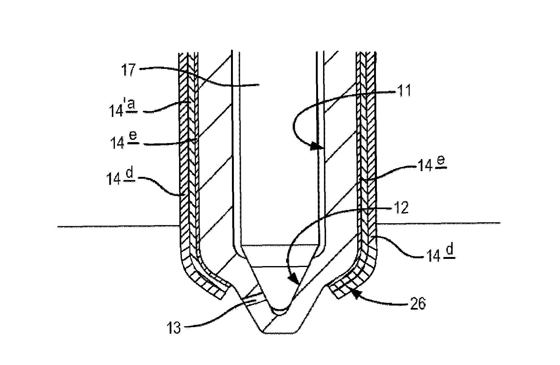
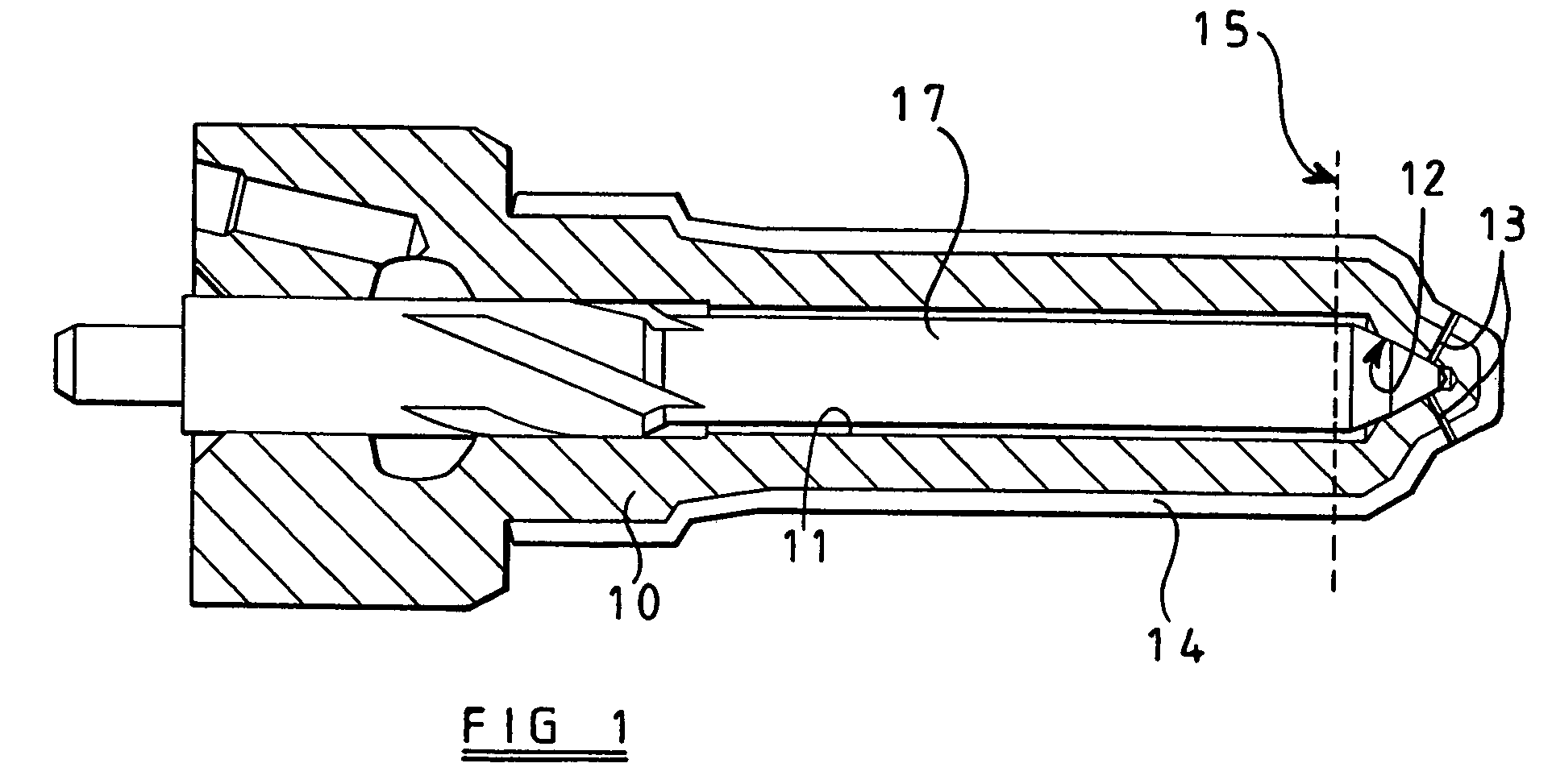
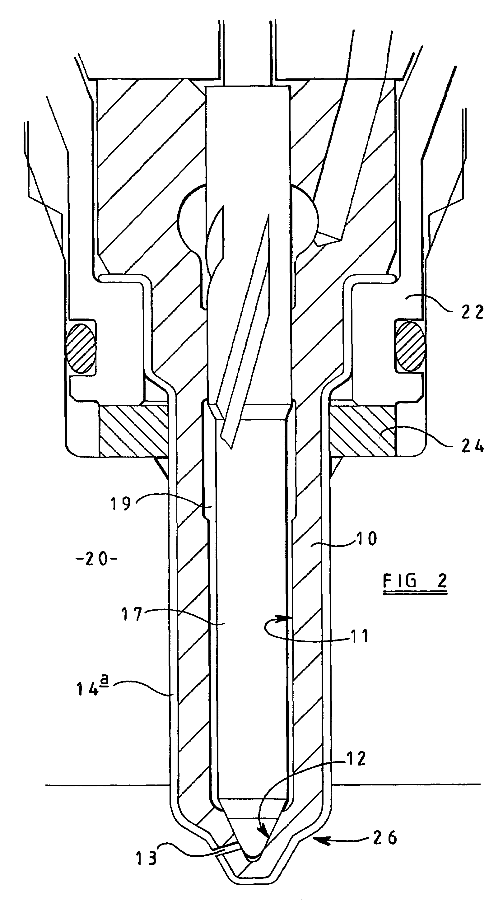
[0031]The injection nozzle illustrated in the accompanying drawings comprises a nozzle body 10 having a blind bore 11 formed therein, the blind bore 11 being supplied with fuel under pressure from a suitable source, for example the common rail of a common rail fuel system. The blind bore 11 is shaped to define, adjacent the blind end thereof, a seating surface 12. In use, a valve needle 17 is slidable within the bore 11. The valve needle 17 is shaped for engagement with the seating surface 12 to control communication between a delivery chamber defined between the bore 11 and the valve needle 17 upstream of the line of engagement between the valve needle 17 and the seating surface 12, and at least one outlet opening 13 which communicates with the bore 11 downstream of the seating surface 12. It will be appreciated that when the valve needle 17 engages the seating surface 12, then fuel is unable to flow from the delivery chamber to the outlet opening(s) 13, thus fuel injection does no...


PUM


Abstract

An injection nozzle for use in delivering fuel to a combustion space, the injection nozzle comprising a nozzle body, at least a part of which is provided with a first coating arranged so as to reduce the temperature of at least a part of the nozzle body, in use. The coating may have either a higher or lower thermal conductivity than the thermal conductivity of the nozzle body.

Description

[0001]This application is a continuation of U.S. application Ser. No. 09 / 654,458, filed Sep. 1, 2000 now abandoned.TECHNICAL FIELD[0002]This invention relates to an injection nozzle suitable for use in a fuel injector for use in the delivery of fuel under high pressure to a combustion space of a compression ignition internal combustion engine.BACKGROUND OF THE INVENTION[0003]An injection nozzle is exposed, in use, to the temperature within the engine cylinder or other combustion space. As a result, the parts of the injection nozzle which are exposed to such temperatures, for example the seating surface, must be able to withstand such temperatures without significant degradation which would otherwise result in an undesirable reduction in the service life of the injection nozzle. Further, the deposition of fuel lacquer within the injection nozzle, which can undesirably effect, for example, the fuel flow rate through the injector, is accelerated where the nozzle is exposed to high oper...

Claims


Application Information

Patent Timeline
Patent Type & Authority Patents(United States)
IPC IPC(8): B05B1/24F02M61/16F02M61/18
CPCF02M61/16F02M61/166F02M61/18F02M2200/06
Inventor LAMBERT, MALCOLM DAVID DICKNANDY, MODHUGREEN, ALAN CONWAY
Owner DELPHI TECH IP LTD
Why Eureka
Try Eureka