Fluid coupler and a device arranged with the same

a technology of fluid coupler and device, which is applied in the direction of thin material processing, semiconductor devices, printing, etc., can solve the problems of increasing difficulty in ensuring both functions, and requiring significant assembly tolerances

Inactive Publication Date: 2008-02-19
XEROX CORP
View PDF16 Cites 4 Cited by
  • Summary
  • Abstract
  • Description
  • Claims
  • Application Information

AI Technical Summary

Benefits of technology

[0076]In summary, some advantages of the present invention include the following:

Problems solved by technology

It is difficult to ensure both functions are satisfied, especially at higher densities.
Material flow (squeeze out) can obstruct these features, thus requiring significant assembly tolerances and careful assembly.
All of these aspects become increasingly difficult as multiple unique material interfaces are needed.

Method used


Image

  • Fluid coupler and a device arranged with the same
  • Fluid coupler and a device arranged with the same
  • Fluid coupler and a device arranged with the same

Examples


Embodiment Construction

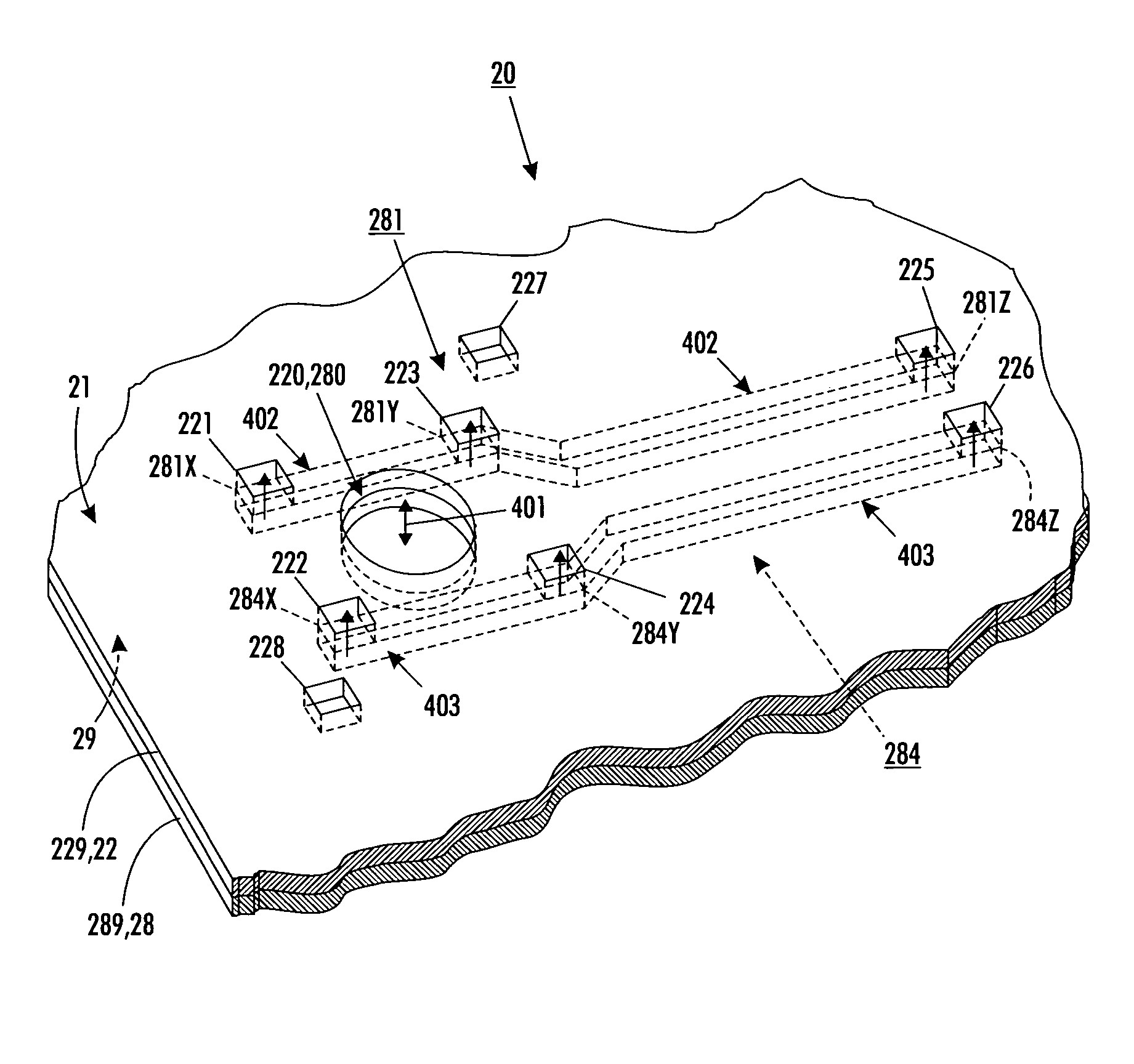
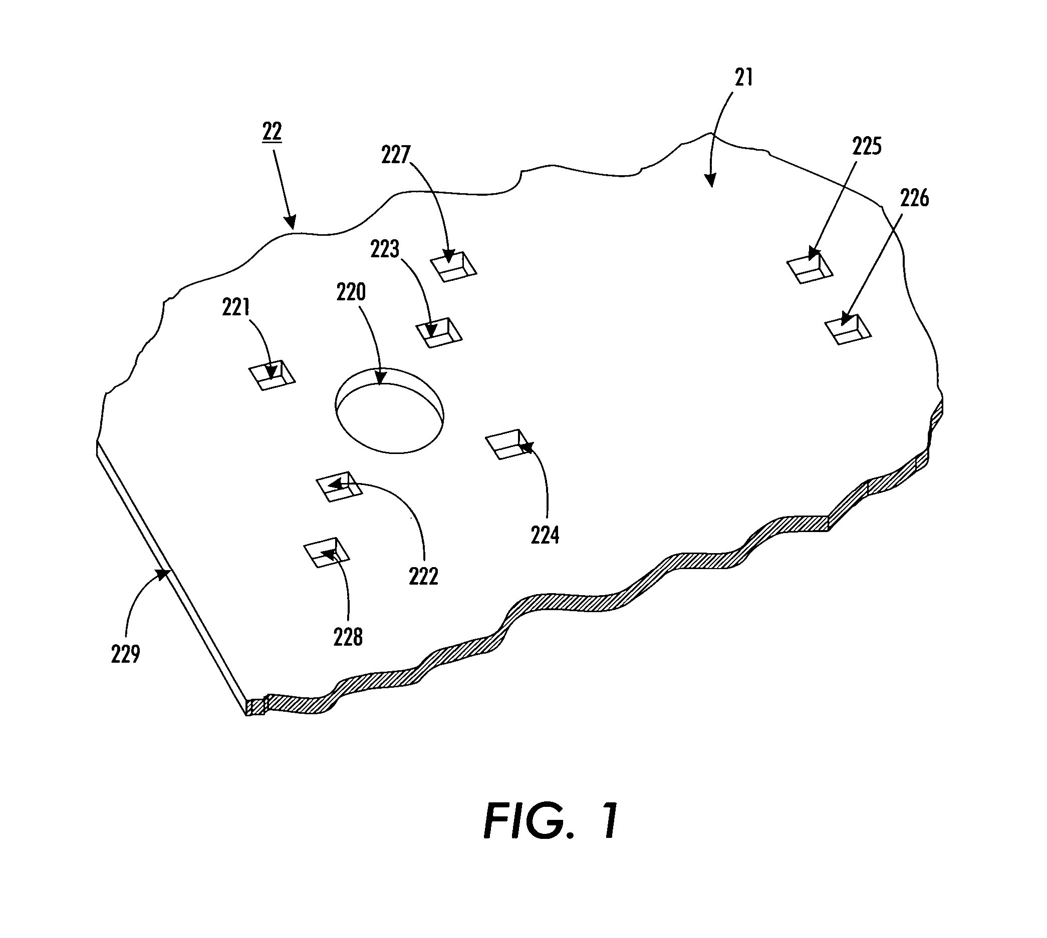
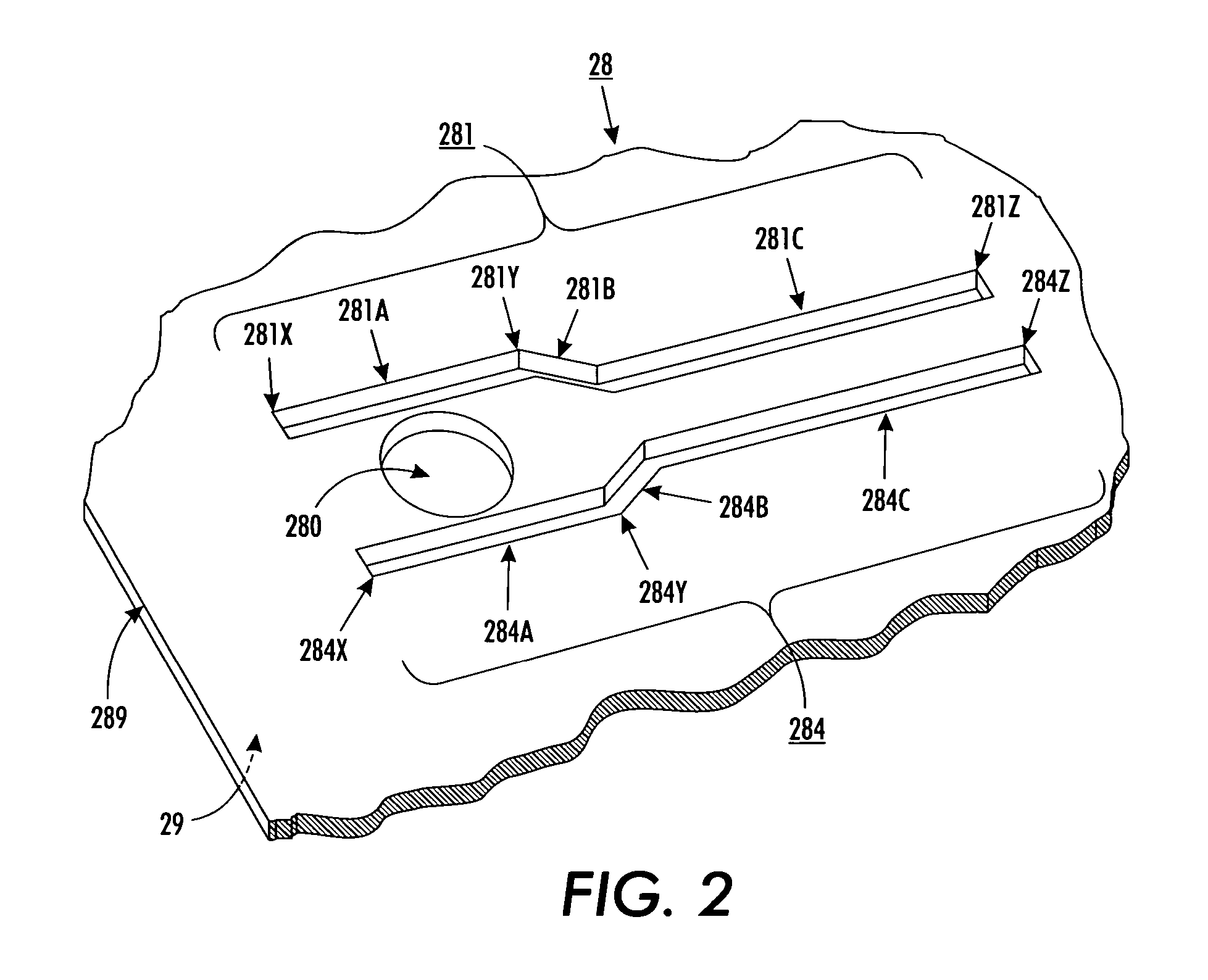
[0030]Briefly, a fluid coupler comprises plural film layers disposed on the substrate top surface of an included substrate. The plural film layers are disposed with respect to one another to define a top film layer and a bottom film layer. Each film layer includes two opposing film layer sides with a corresponding film layer thickness or spacing therebetween. Each film layer further includes regions that are devoid of film material, thus forming film layer cavities with corresponding cavity openings in both of the film layer's sides. Each film layer has its cavities disposed to provide fluid coupling with its adjacent film layer or with its adjacent film layers, as the case may be. The plural film layers thus form a film layer traverse channel coupling the top film layer and the bottom film layer. The plural film layers further form one or more film layer lateral channels coupling cavity openings in the top film layer. The film layer traverse channel fluidly couples with a substrate...


PUM


Abstract

Plural film layers are disposed on a substrate. Each film layer has regions devoid of film material, thus forming film layer cavity openings. Each film layer has its cavities arranged to provide fluid coupling with its adjacent film layer or layers. The film layer cavities form a traverse channel coupling the top and bottom film layers and also one or more lateral channels coupling cavity openings in the top film layer. The film layer traverse channel couples with a substrate channel that extends from the substrate top surface to one or more of its other surfaces. A device such as a fluid dispenser, fluid ejector, sensor or bioprocessing device is disposed on the top film layer and fluidly coupled to the plural film layers traverse and lateral channels. The traverse channel and the one or more lateral channels are arranged to transport or flow one or more fluids.

Description

INCORPORATION BY REFERENCE OF OTHER U.S. PATENTS[0001]The disclosures of the following fifteen (15) U.S. patents are hereby incorporated by reference, verbatim, and with the same effect as though the same disclosures were fully and completely set forth herein:[0002]John R. Andrews et al., “Precision laser cutting of adhesive members”, U.S. Pat. No. 6,229,114 B1;[0003]John R. Andrews et al., “Methods for forming features in polymer layers”, U.S. Pat. No. 6,596,644 B1;[0004]Charles P. Coleman et al., “Method of fabricating a fluid drop ejector”, U.S. Pat. No. 6,127,198;[0005]Charles P. Coleman et al., “Fluid drop ejector”, U.S. Pat. No. 6,318,841 B1;[0006]Frank C. Genovese et al., “Magnetically actuated ink jet printing device”, U.S. Pat. No. 6,234,608 B1;[0007]Arthur M. Gooray et al., “Magnetic drive systems and methods for a micromachined fluid ejector”, U.S. Pat. No. 6,350,015 B1;[0008]Arthur M. Gooray et al., “Micromachined fluid ejector systems and methods”, U.S. Pat. No. 6,367,9...

Claims


Application Information

Patent Timeline
Patent Type & Authority Patents(United States)
IPC IPC(8): B41J2/05
CPCB41J2/1433B41J2/162B41J2/1632B41J2/1634B41J2/1623Y10T428/24322
Inventor NYSTROM, PETER J.ANDREWS, JOHN R.
Owner XEROX CORP
Why Eureka
Try Eureka