Iris pattern recognition and alignment

a technology of iris pattern recognition and alignment, applied in the field of laser vision correction and laser eye surgery, can solve the problems of degrading vision quality, complication, and pupil constricting, and achieve the effect of accurate laser treatment and accurate positioning

Inactive Publication Date: 2008-02-19
BAUSCH & LOMB INC +1
View PDF3 Cites 60 Cited by
  • Summary
  • Abstract
  • Description
  • Claims
  • Application Information

AI Technical Summary

Benefits of technology

[0013]In another embodiment of the invention, an improvement is directed to a system for diagnostic and therapeutic laser eye treatment where it is intended to align a diagnostic iris image and a treatment iris image via iris pattern recognition techniques to effect a more accurate laser treatment, characterized in that the system includes a controllable, visible illumination component by which a controlled amount of visible illumination can be directed either to the patient's eye being examined or the patient's other eye (not being examined) with the effect of changing in a controlled way the pupil size of the eye under examination. A diagnostic image capture device is used to obtain a sequential plurality of diagnostic iris images, each having a different pupil diameter ranging between a dilated pupil size and a constricted pupil size corresponding to the level of controlled visible illumination. Although, as stated above, an iris recognition landmark present in both the dilated pupil diagnostic iris image and the constricted pupil diagnostic iris image cannot typically be tracked between these two image extremes, at least an indicia of the iris recognition landmark can be tracked through the sequential plurality of diagnostic iris images so that the dilated pupil diagnostic iris image can ultimately be correlated with the constricted pupil diagnostic iris image. The improved system further includes a diagnostic device for obtaining an appropriate diagnostic measurement of the patient's eye wherein this device is cooperatively associated with the illumination control device and the diagnostic image capture device. Further included is a means for exporting at least one of the diagnostic iris images to the laser treatment part of the system, and means for aligning the ultimate constricted pupil diagnostic iris image with the constricted pupil treatment image so that a more accurately positioned laser treatment can be applied to the eye. In an aspect of this embodiment, the means for aligning the plurality of diagnostic iris images and aligning an ultimate diagnostic image with the treatment iris image includes processing hardware and soft

Problems solved by technology

It is well known that higher order aberrations in addition to lower order aberrations degrade vision quality.
At the laser treatment stage, however, the nature and amount of light striking the eye from light sources in the treatment system environment typically causes the pupil to constrict.
A complication arises because the center location of the dilated pupil is shifted from the center location of the constricted pupil.
Thus, a calculated laser treatment centered on the constricted (treatment) pupil, based upon a diagnostic measurement aligned to the center of the dilated pupil, is likely to be applied at an incorrect location on the cornea.
Another complication arises from the fact that the position of a patient's eye in a sitting position rotates about an axis when the patient is in a treatment (supine) position.
This is problemati

Method used


Image

  • Iris pattern recognition and alignment
  • Iris pattern recognition and alignment
  • Iris pattern recognition and alignment

Examples


Embodiment Construction

[0021]While the present invention is described with reference to illustrative embodiments for particular applications, it should be understood that the present invention is not so limited. Those having ordinary skill in the art and access to the teachings provided herein will recognize additional modifications, applications, and embodiments within the scope thereof and additional fields in which the invention will be of significant utility without undue experimentation.

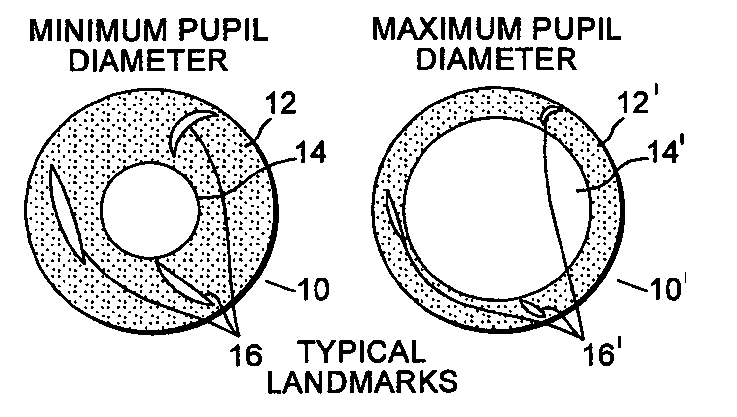
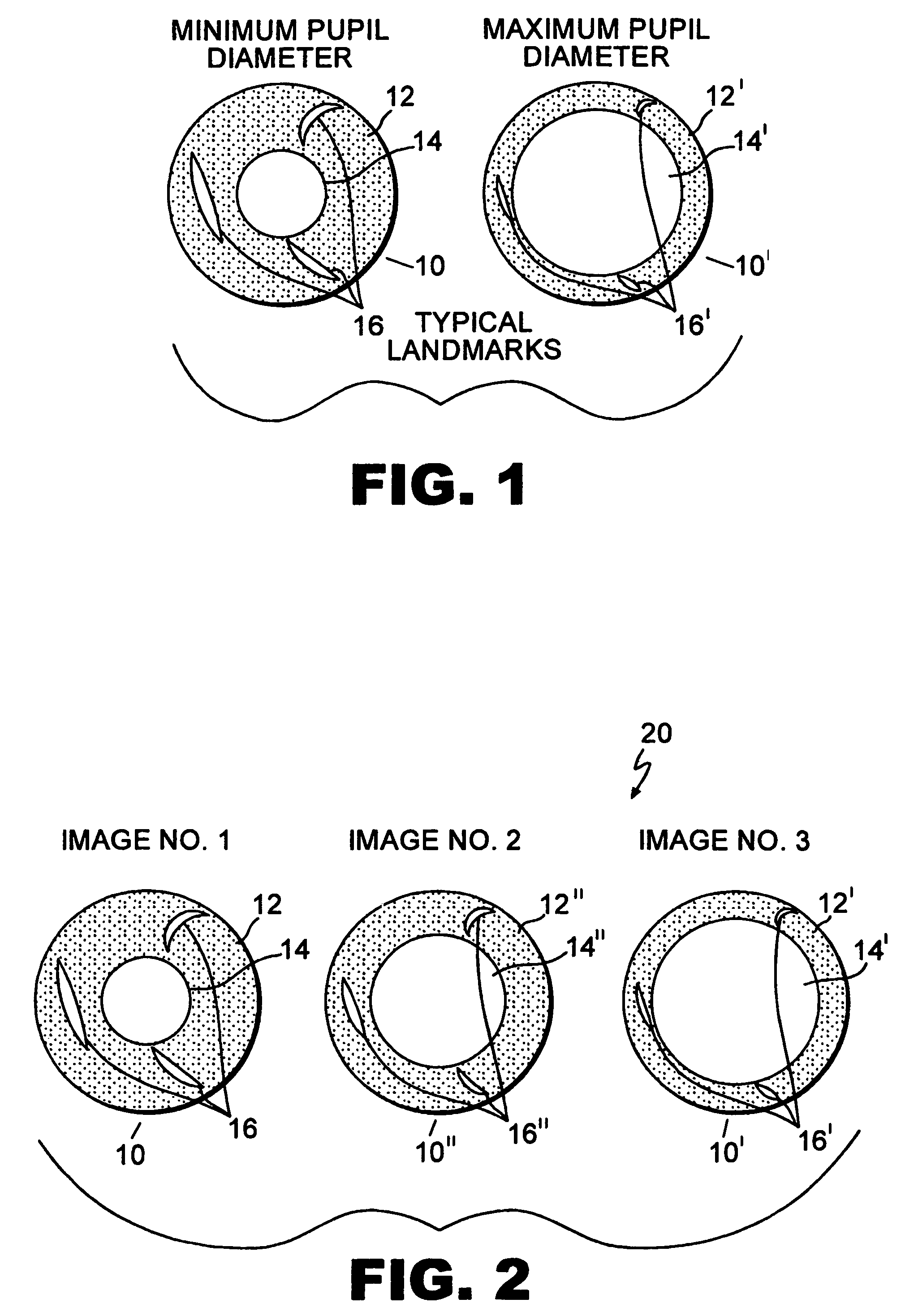
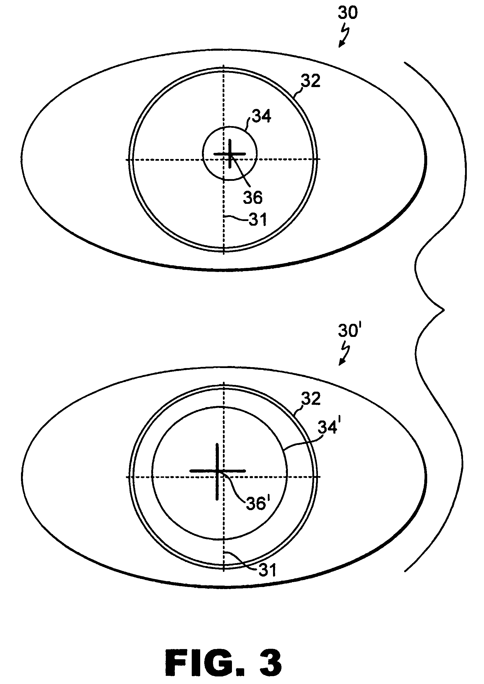
[0022]The invention is directed to methods and systems providing alignment between diagnostic images of the eye and treatment images of the eye that result in greater accuracy of the laser treatment and, therefore, greater patient satisfaction.

[0023]An embodiment of the invention is described below in accordance with FIGS. 1 and 2. Systems and devices are known which use iris pattern recognition for identifying eye structures and for aligning diagnostic and therapeutic images for eye surgery. For example, PCT / EP00 / 103...


PUM


Abstract

Apparatus and methods are described for aligning diagnostic and therapeutic iris images, via iris pattern recognition, for effecting more accurate laser treatment of the eye. A method for aligning a dilated pupil diagnostic iris image associated with a diagnostic measurement for calculating a laser treatment, with a constricted pupil diagnostic iris image, by identifying an iris landmark that is not identifiable solely between the two images, includes a sequential plurality of diagnostic iris images of varying pupil size such that the iris landmark can be tracked between the two images. The aligned, constricted pupil diagnostic image can then be aligned with a constricted pupil treatment image and the ablation pattern rotated accordingly. Limbal edge detection is used in the diagnostic images to provide pupil center translation information for translational alignment of the laser treatment. An improved aberrometer is disclosed having a variable visible illumination fixation target for controlling pupil size for the diagnostic images. A diagnostic and therapeutic laser eye treatment system is described incorporating the apparatus and method embodiments of the invention.

Description

[0001]This application is related to PCT EP00 / 10373.BACKGROUND OF THE INVENTION[0002]1. Field of the Invention[0003]This invention relates generally to the field of laser vision correction and laser eye surgery, and more specifically to a device, system and methods for alignment of diagnostic and treatment images of the eye for more accurate surgical outcomes and improved patient satisfaction.[0004]2. Description of Related Art[0005]The popularity of photorefractive surgery for the correction or enhancement of vision continues to rise. Techniques such as photorefractive keratotomy (PRK), laser in situ keratomileusis (LASIK), laser epithelial keratomileusis (LASEK) and variations thereof are now commonly used to correct the effects of nearsightedness (myopia), farsightnesses (hyperopia), and astigmatism, in addition to more traditional retinal surgery and other ocular surgical procedures. These vision defects are typically treated by laser ablating the cornea to steepen or flatten it...

Claims


Application Information

Patent Timeline
IPC IPC(8): A61B3/10A61B3/15A61B5/117A61F9/007G06K9/00
CPCA61B3/152A61B5/117G06K9/00604A61B5/1171G06V40/19A61B3/15
Inventor GROTEHUSMANN, ULFYOUSSEFI, GERHARD
Owner BAUSCH & LOMB INC
Why Eureka
Try Eureka