
Viscosity controller for ink pad printers

a technology of viscosity controller and ink pad printer, which is applied in the direction of process and machine control, instruments, transportation and packaging, etc., can solve the problems of prone to methodological errors, laborious methods, and easy abrupt changes in the viscosity of the surface preparation, and achieve fast color changeover and cleanup, and increase the productivity of the printer

Inactive Publication Date: 2008-02-19
AUTOMATED INDAL SYST
View PDF18 Cites 12 Cited by
  • Summary
  • Abstract
  • Description
  • Claims
  • Application Information

AI Technical Summary

Benefits of technology

[0006]It is an object of the present invention to provide a viscosity controller for ink pad printers that increases the productivity of the printers.
[0007]It is another object of the present invention to provide a viscosity controller for ink pad printers that gives a consistent print quality throughout the particular printing process or run.
[0008]It is still another object of the present invention to provide a viscosity controller for ink pad printers that overcomes physical conditions and factors such as humidity and pressure that can impair the printing process.
[0009]It is still yet another object of the present invention to provide a viscosity controller for ink pad printers that permits fast color changeover and cleanup.

Problems solved by technology

This occurs in pad ink printing where it is known that the surface viscosity of the preparation is susceptible to abrupt changes.
However, these methods are laborious and prone to methodological errors.

Method used


Image

  • Viscosity controller for ink pad printers
  • Viscosity controller for ink pad printers
  • Viscosity controller for ink pad printers

Examples


Embodiment Construction

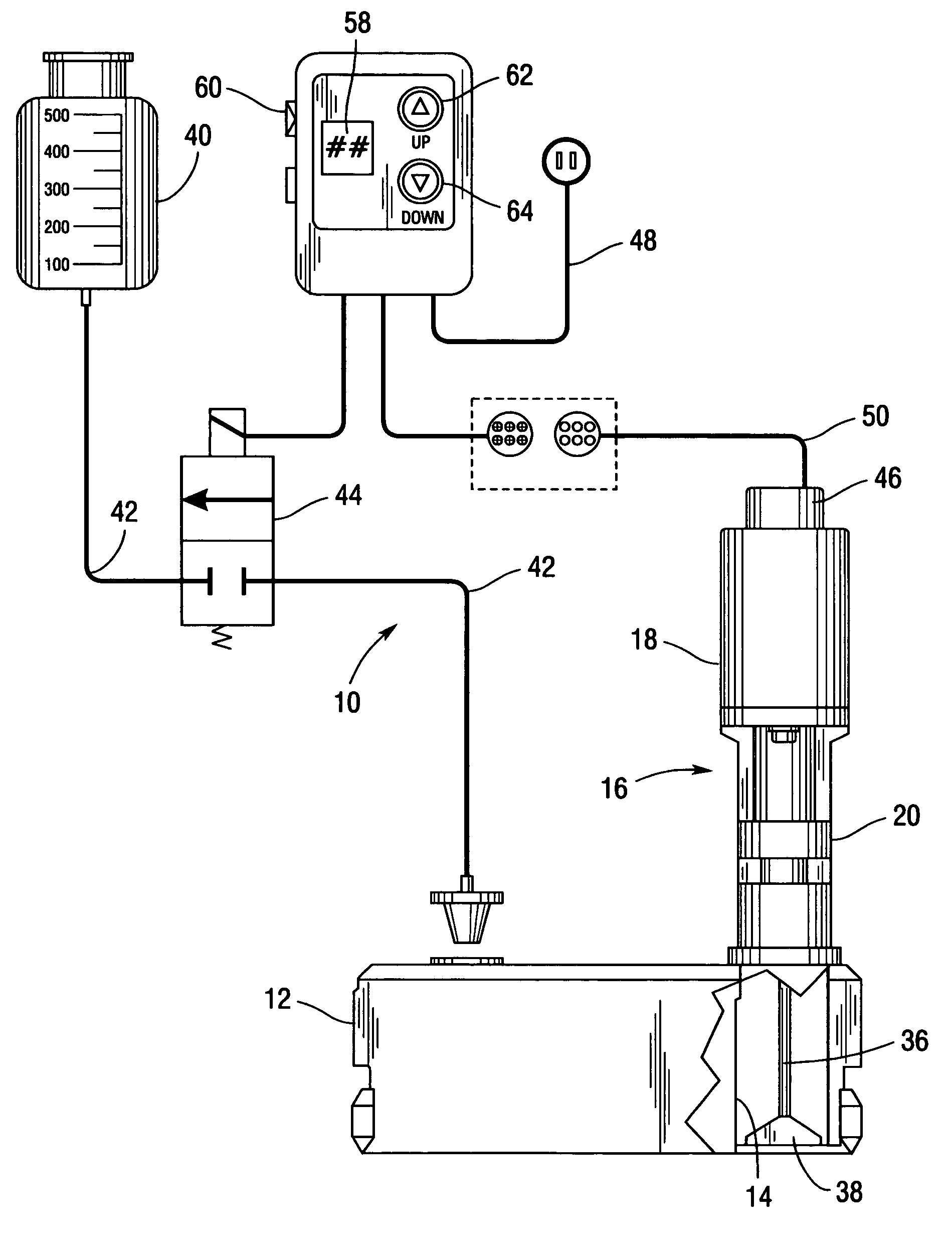
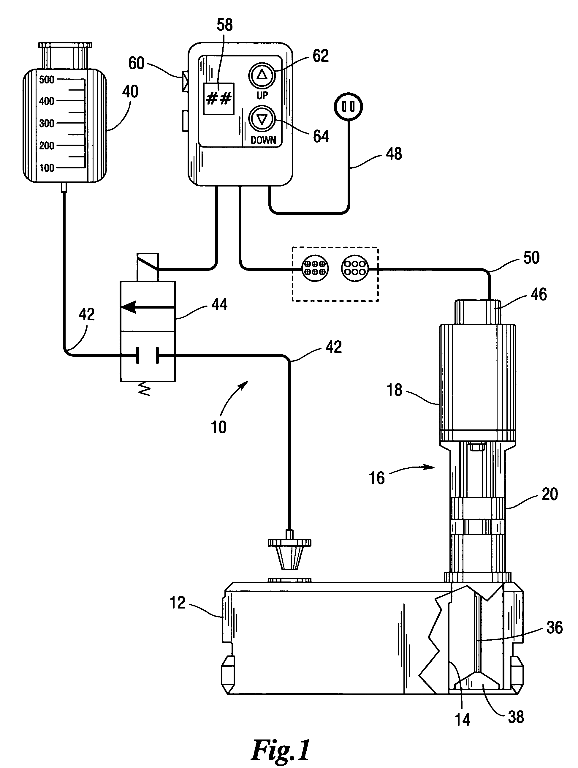
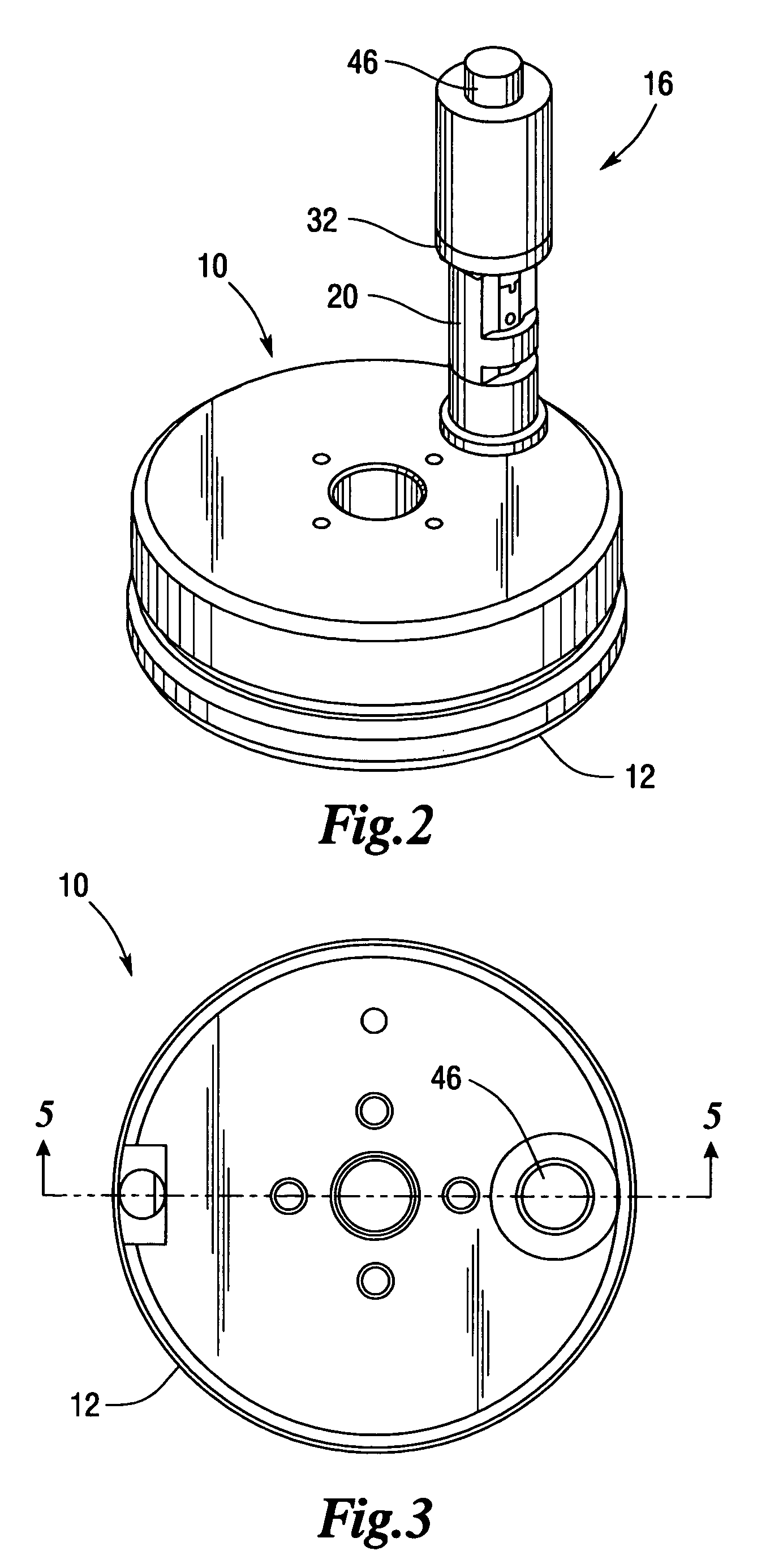
[0025]Illustrated in FIGS. 1 through 9 is a viscosity controller 10 for monitoring, controlling and incrementally adjusting the viscosity of ink used by a pad printing apparatus throughout a printing application. Viscosity controller 10 of the present invention does not physically measure the amount of ink in the pad cup, but, instead, incrementally adjusts the viscosity of the ink, on a continual basis throughout the work shift, to maintain ink viscosity at a preset or predetermined level or value particular for that application. Illustrated in FIGS. 1 through 6 are the primary structural elements of the preferred embodiment of viscosity controller 10 of the present invention. Thus, a sealed ink cup 12 includes a reservoir 14 for holding the ink that is used in the printing process or application. Ink cup 12 includes structural elements located at the cup center for attaching ink cup 12 to the pad printing machines and as these are conventional in the field they are not shown. Moun...


PUM

PropertyMeasurementUnit
viscosityaaaaaaaaaa
surface areaaaaaaaaaaa
timeaaaaaaaaaa

Abstract

A viscosity controller automatically monitoring and controlling the viscosity of ink in a pad printing device on a continuous basis throughout the printing process includes a sealed ink cup having mounted thereon a motor with a paddle extending into the ink cup, a solvent tank in flow communication with the ink cup, and a valve for allowing selective amounts of the solvent to be added to the ink cup from the solvent tank. The viscosity of the ink in the cup creates torque on the paddle that affects the number of encoder pulses that are counted per time period by a motor encoder mounted to the motor, and the encoder pulses are counted and compared to a look up table stored in the microprocessor of the controller to determine if the valve should be opened to add diluting agent to the ink cup so that the ink viscosity can be maintained at a preset or predetermined value.

Description

FIELD OF THE INVENTION[0001]The present invention pertains to the regulation of the viscosity of ink in an ink pad printing application, and more particularly pertains to a viscosity controller for continuously monitoring, controlling and incrementally adjusting the viscosity of ink for a pad printing apparatus throughout the printing process.BACKGROUND OF THE INVENTION[0002]In various kinds of pad printing and press printing operations determining the dilutability or viscosity of the relevant preparation is a crucial factor in achieving high print quality. Generally before the printing operation commences a value that may be referred to as a viscosity reference value is set or determined as the value at which the ink viscosity should be maintained. It is common for the viscosity of the preparation to change considerably during the printing application, and thus a diluting agent must be added to the preparation for maintaining the desired viscosity. This occurs in pad ink printing w...

Claims


Application Information

Patent Timeline
Patent Type & Authority Patents(United States)
IPC IPC(8): B01F15/02G01N11/14G05D24/00
CPCB01F7/0025B01F15/00201B01F15/00246B01F15/0408G01N11/14G01N33/32G01N2011/0046Y10T137/2506B01F27/112B01F35/212B01F35/2136B01F35/82
Inventor HAHN, RONALDBULLOCK, STEVEHEIGES, ROBERT W.
Owner AUTOMATED INDAL SYST
Learn More