Semiconductor manufacturing system having a vaporizer which efficiently vaporizes a liquid material

Inactive Publication Date: 2008-02-19
TOKYO ELECTRON LTD
View PDF19 Cites 24 Cited by
  • Summary
  • Abstract
  • Description
  • Claims
  • Application Information

AI Technical Summary

Benefits of technology

[0013]It is a general object of the present invention to provide an improve

Problems solved by technology

Especially, requirements to the film deposition process have become more severe in association with the progress in a high density and high integration of semiconductor devices.
As a result, the vaporizing chamber 10 cannot be set in a sufficient vacuum condition due to a pressure loss related to the configuration of the vaporizing chamber 10 even if a strong vacuum force is generated by the film deposition apparatus.
Additionally, there is a problem in that a smooth flow of the material gas cannot be achieved due to

Method used


Image

  • Semiconductor manufacturing system having a vaporizer which efficiently vaporizes a liquid material
  • Semiconductor manufacturing system having a vaporizer which efficiently vaporizes a liquid material
  • Semiconductor manufacturing system having a vaporizer which efficiently vaporizes a liquid material

Examples


second embodiment

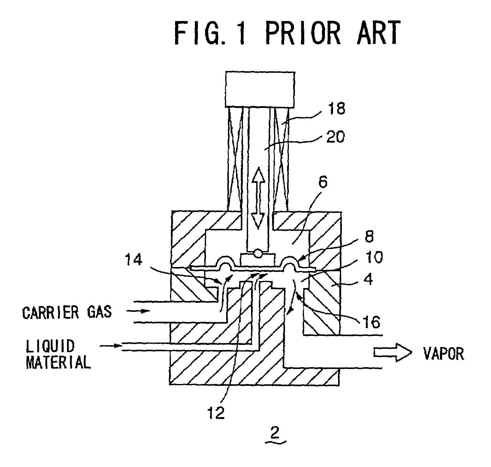
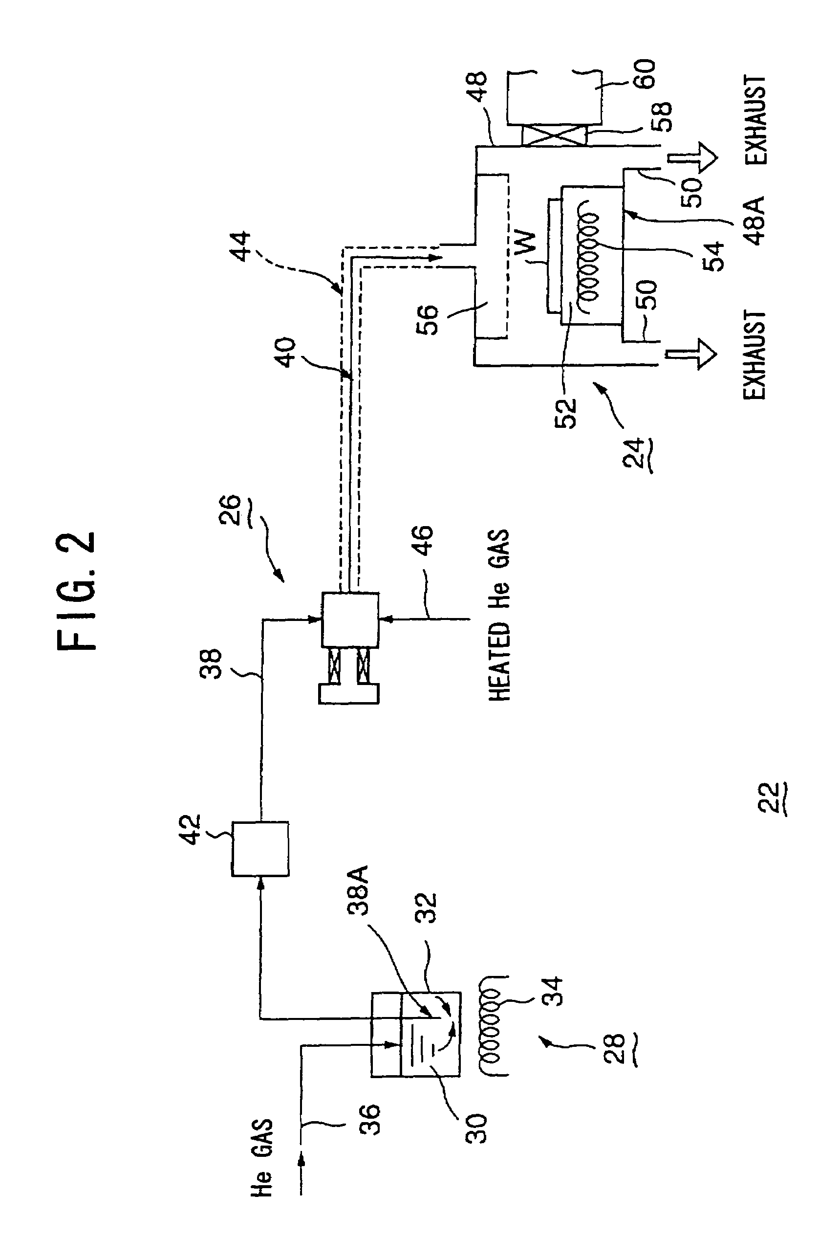
[0071]A description will now be given, with reference to FIG. 10, of a vaporizer according to the present invention. In FIG. 10, parts that are the same as the parts shown in FIG. 3 are given the same reference numerals, and descriptions thereof will be omitted.

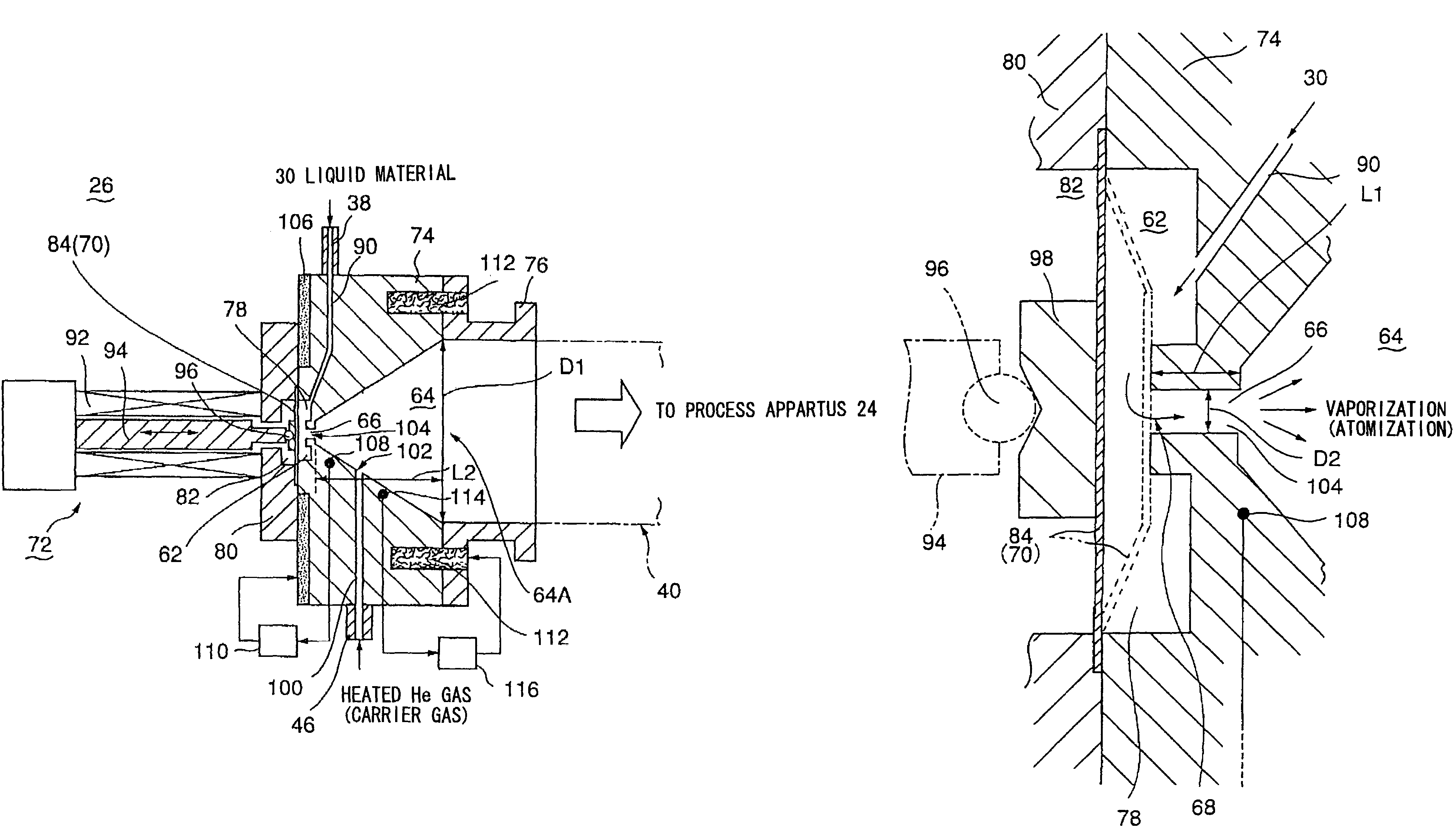
[0072]The vaporizer 26A according to the second embodiment of the present invention has the same structure as the vaporizer 26 according to the above-mentioned first embodiment except for the structure for injecting a carrier gas being changed. That is, although the carrier gas is injected from the wall surface of the vaporizing chamber 64 in the structure of the vaporizer 26 according to the first embodiment, the carrier gas in the vaporizer 26A according to the present embodiment is injected toward a position directly under the outlet port of the small aperture 66 from the surrounding area of the outlet port of the small aperture 66.

[0073]As shown in FIG. 10, an end of the carrier gas passage 100 provided in the vaporizer b...

third embodiment

[0080]A description will now be given, with reference to FIG. 11, of a vaporizer according to the present invention. In FIG. 11, parts that are the same as the parts shown in FIG. 3 are given the same reference numerals, and descriptions thereof will be omitted.

[0081]The vaporizer 26B according to the third embodiment of the present invention has the same structure as the vaporizer 26 according to the above-mentioned first embodiment except for the structure for injecting a carrier gas being changed. That is, although the carrier gas is injected from the wall surface of the vaporizing chamber 64 in the structure of the vaporizer 26 according to the first embodiment, the carrier gas in the vaporizer 26B according to the present embodiment is injected toward the outlet port of the small aperture 66 from under the outlet port of the small aperture 66 so as to promote the atomization of the liquid material.

[0082]As shown in FIG. 11, an end of the carrier gas passage 100 provided in the ...


PUM

PropertyMeasurementUnit
Diameteraaaaaaaaaa
Diameteraaaaaaaaaa
Diameteraaaaaaaaaa

Abstract

A vaporizer can efficiently vaporize a liquid material under a depressurized atmosphere. The liquid material is temporarily stored in a liquid storing chamber, and is supplied to a vaporizing chamber set in the depressurized atmosphere via a small aperture. An inlet of the liquid storing chamber is opened or closed by a valve body, which is moved by an actuator controlling a degree of opening of the valve body.

Description

BACKGROUND OF THE INVENTION[0001]1. Field of the Invention[0002]The present invention generally relates to a semiconductor manufacturing system and, more particularly, to a vaporizer for vaporizing a liquid material to produce a gas to be used in a semiconductor manufacturing process.[0003]2. Description of the Related Art[0004]Generally, a semiconductor device is produced by processing a semiconductor wafer by repeating a film deposition process and a pattern etching process. Especially, requirements to the film deposition process have become more severe in association with the progress in a high density and high integration of semiconductor devices. For example, there is a demand for a thinner film with respect to an extremely thin film such as an insulating film for producing a capacitor or a gate in the semiconductor device. Also there is a demand for a thinner film with respect to an electrode film or a wiring pattern film. In a case of the wiring pattern film, there is suggest...

Claims


Application Information

Patent Timeline
IPC IPC(8): C23C16/00F16K3/00F16K31/02H01L21/306C23C16/448F16K7/14F16K31/06H01L21/18H01L21/205
CPCC23C16/4481F16K7/14F16K31/06Y10T137/87571Y10T137/87676H01L21/18
Inventor KOJIMA, YASUHIKOMORI, HIROYUKIONO, HIROFUMI
Owner TOKYO ELECTRON LTD
Why Eureka
Try Eureka