Xerographic micro-assembler

a micro-assembler and assembler technology, applied in the direction of individual semiconductor device testing, semiconductor/solid-state device testing/measurement, instruments, etc., can solve the problems of limiting process, incompatibility with micron-sized integrated circuit structures, and severe limitations on the shape, size and distribution of components

Active Publication Date: 2008-02-19
XEROX CORP
View PDF17 Cites 71 Cited by
  • Summary
  • Abstract
  • Description
  • Claims
  • Application Information

AI Technical Summary

Problems solved by technology

However, severe limitations exist on the shape, size, and distribution of the components.
Furthermore, the structures disclosed by Yando typically possess millimeter-sized dimensions and are therefore generally incompatible with micron-sized integrated circuit structures.
Such a process is limiting because of the need for the human or robotics arm.
The human or robotics arm assembles each packaged device onto the substrate one-by-one and not simultaneously, thereby limiting the efficiency and effectiveness of the operation.
Moreover, the method uses centimeter-sized devices (or packed surface mount integrated circuits), and has little applicability to the assembly of micron-sized objects.
A limitation to the method is that it requires an apparatus capable of vibrating the structures, or an apparatus for pulsating air through the apertures.
Moreover, the method described relies upon centimeter-sized dies and has little applicability to the assembly of micron-sized objects.
The method is limited because of the need for a shaking apparatus for the electromagnetic shaking step.
Moreover, the method is solely in context to electrode pedestals and silicon wafers, thereby limiting the use of such method to these structures.
A limitation with the method includes having to provide an apparatus capable of vibrating particles with electrostatic forces.
Moreover, the method of Cohn tends to damage the integrated circuits by mechanically vibrating them against each other.
Accordingly the method typically becomes incompatible with a state-of-art microstructures.
In particular, the George process lacks the ability to orient the micro-objects in specific directions.
Further, the method is not particularly amenable to efficiently assembling a micro-assembly that utilizes a number of different types of micro-objects.

Method used


Image

  • Xerographic micro-assembler
  • Xerographic micro-assembler
  • Xerographic micro-assembler

Examples


generalized example embodiment

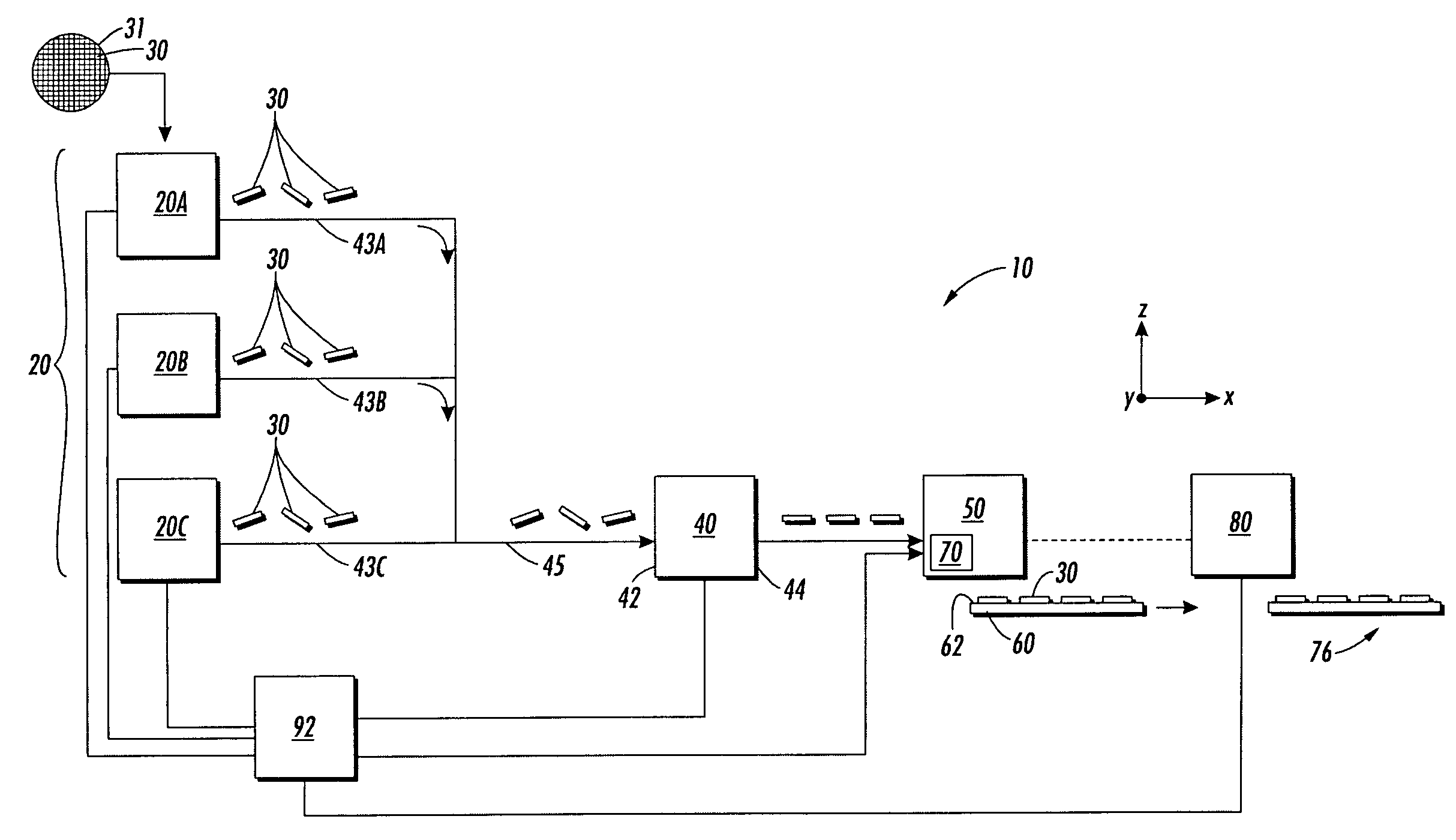
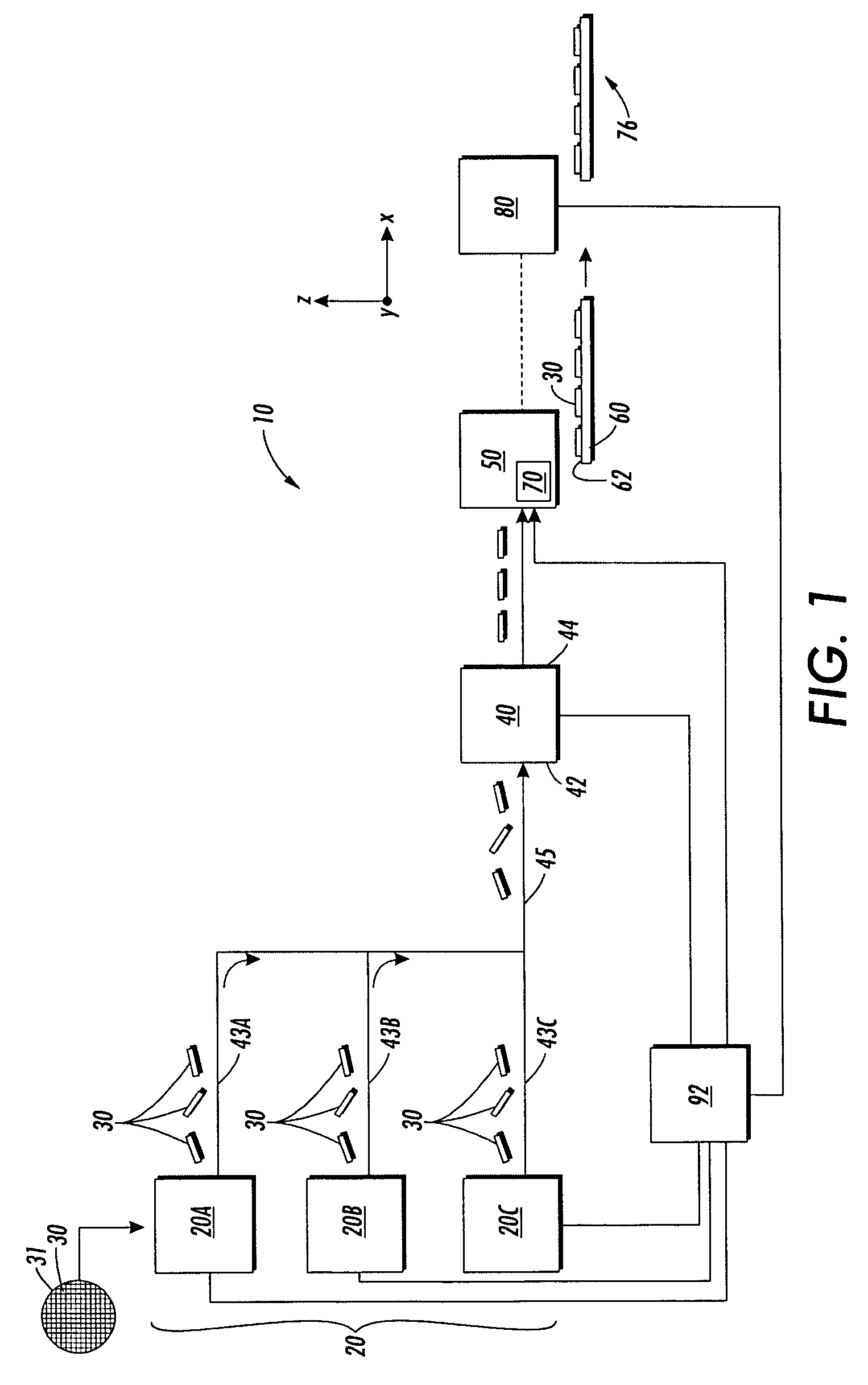
[0034]FIG. 1 is a schematic side view of an example embodiment of a micro-assembler 10 according to the present invention. Micro-assembler 10 includes one or more pre-processing units 20 (e.g., three such units 20A, 20B and 20C) adapted to modify, form or otherwise process different types (sets) of micro-objects 30, which are described below.

[0035]In an example embodiment reflecting the simplest case, pre-processing units 20 serve as reservoirs for micro-objects 30 that are pre-formed, e.g., as micro-chip-based micro-objects formed in a semiconductor fabrication facility using, for example, standard semiconductor processing techniques. In another example embodiment, pre-processing units 20 are adapted to form the micro-objects from a larger object, such as a semiconductor wafer having the micro-objects formed therein. FIG. 1 illustrates an example of this embodiment wherein a wafer 31 is provided to one of the pre-processing units for dicing into individual micro-objects 30. In anot...


PUM

PropertyMeasurementUnit
sizeaaaaaaaaaa
sizeaaaaaaaaaa
chargeaaaaaaaaaa

Abstract

Xerographic micro-assembler systems and methods are disclosed. The systems and methods involve manipulating charge-encoded micro-objects. The charge encoding identifies each micro-object and specifies its orientation for sorting. The micro-objects are sorted in a sorting unit so that they have defined positions and orientations. The sorting unit has the capability of electrostatically and magnetically manipulating the micro-objects based on their select charge encoding. The sorted micro-objects are provided to an image transfer unit. The image transfer unit is adapted to receive the sorted micro-objects, maintain them in their sorted order and orientation, and deliver them to a substrate. Maintaining the sorted order as the micro-objects are delivered to the substrate may be accomplished through the use of an electrostatic image, as is done in xerography. The substrate with the micro-objects is further processed to interconnect the micro-objects—through electrical wiring, for example—to form the final micro-assembly.

Description

FIELD OF THE INVENTION[0001]The field of the invention relates to micro-assembler systems and methods for forming micro-assemblies from micro-objects.BACKGROUND OF THE INVENTION[0002]The background of the invention relates to aspects of xerography as well as micro-assembly techniques used for fabricating microstructures and microdevices, generally referred to herein as “micro-assemblies.”[0003]The invention described below utilizes xerographic techniques as well as micro-assembly fabrication techniques. Accordingly, background information on xerography and micro-assembly fabrication techniques is provided below.Xerography[0004]In xerography (also known as electrophotography, electrostatographic printing, and colloquially as “photocopying”), a uniform electrostatic charge is placed upon a photoreceptor surface. The charged surface is then exposed to a light image of an original object to selectively dissipate the charge to form a latent electrostatic image of the original. The image ...

Claims


Application Information

Patent Timeline
Patent Type & Authority Patents(United States)
IPC IPC(8): G01R31/26H01L21/66
CPCH01L21/67271H01L21/67294H01L25/50H01L24/95H01L21/67282Y10T29/53174H01L2224/95085H01L2224/95144H01L2224/95145H01L2924/1461Y10T29/4913Y10T29/49133Y10T29/53278Y10T29/53004Y10T29/53178Y10T29/5313H01L2924/00H01L2924/14H01L2224/95101
Inventor LU, JENG PINGCHOW, EUGENE M.
Owner XEROX CORP
Why Eureka
Try Eureka