Optical based performance improvement for an optical illumination configuration

a technology of optical illumination and optical based performance improvement, applied in the field of optical technology, can solve the problems of less efficient light source use, achieve the effects of improving battery life, reducing power consumption and component efficiency gains, and increasing efficiency in the illumination system

Inactive Publication Date: 2008-02-19
LOGITECH EURO SA
View PDF55 Cites 19 Cited by
  • Summary
  • Abstract
  • Description
  • Claims
  • Application Information

AI Technical Summary

Benefits of technology

[0012]There are many benefits and advantages of the present invention. One advantage is that less LED current is required for a higher optical power on the table surface due to an illumination yield gain. This helps to prolong battery life for a wireless product. Another advantage is removing a need for a high efficiency LED to compensate for an inefficient lighting system. This helps reduce costs because a less efficient light source may be used. Another advantage is reducing mechanical dimensions for the system thereby increasing design flexibility and reducing cost. For example, there is a significant reduction in the size of the optical portion of an illumination system. The reduction in size permits a smaller lens part to be used, which uses less optical material in manufacturing, less injection time and a smaller mold, and therefore, reduces the cost. Another advantage is that the illumination area position robustness with respect to the target area is increased. Another advantage could be an increase in depth of field because a smaller aperture can be used with the imaging lens. An increase in depth of field allows for greater mechanical tolerances. Another advantage is a reduction in exposition time, the sensor being illuminated with the required amount of energy in a shorter amount of time. The time reduction factor is equivalent to the illumination yield gain.
[0014]In one embodiment of the present invention, losses in the system are reduced by the illumination light pipe, thus making it more efficient. The losses are reduced by the light pipe with a conical shape that reduces the region or surfaces where rays are not under the TIR condition. In one embodiment, instead of using a double prism, a conical (or cylindrical) light pipe is used. The conical light pipe has a larger entrance surface than exit surface. The large entrance surface combined with the light pipe function allows larger position errors for the LED. In one embodiment, a curvatured (e.g. toroidal) entrance surface or exit surface is used. The toroidal shape means that the entrance surface or exit surface has at least two different radii of curvature orthogonal to each other, in a vertical and a horizontal plane. One embodiment has a curvatured surface at each end of the conical light pipe portion. The conical section can be truncated by a first reflective surface. This truncation is advantageous because it allows the LED to be positioned horizontally or obtains the required angle of incidence beam on the target surface. In another embodiment, a second reflective surface also acts to further direct the light toward the surface. The second truncation allows other positions of the LED and further increases design flexibility. In one embodiment, the reflective surfaces combined with the light pipe direct most of the light out the exit surface, forming a twice-truncated cone. In one embodiment the reflective surfaces can be coated with a metallic covering to guarantee reflection of rays not satisfying the TIR condition. In an alternate embodiment, the first reflective surface and the second reflective surface can be removed when the LED is positioned at a predetermined angle.
[0016]As described above, the benefits of the present invention include an improved battery life, for example for an optical cordless mouse, due to reduced power consumption and component efficiency gains. An efficient or powerful light source is not required with the present invention due to increased efficiency in the illumination system. One embodiment of the present invention reduces the length of the optical system, which enables greater industrial design flexibility. Using the present invention allows for the possibility of gaining depth of field by reducing the imaging lens aperture because there is more energy on the surface. The present invention provides a much more robust system to the misalignment between the light source and the illumination lens by providing enough energy on the surface. The present invention allows a reduction of the exposure time of the sensor if the conventional (high efficiency) light source and the driving current are kept the same. The present invention aims at illuminating the surface with a spot that is more uniform.

Problems solved by technology

This helps reduce costs because a less efficient light source may be used.

Method used


Image

  • Optical based performance improvement for an optical illumination configuration
  • Optical based performance improvement for an optical illumination configuration
  • Optical based performance improvement for an optical illumination configuration

Examples


Embodiment Construction

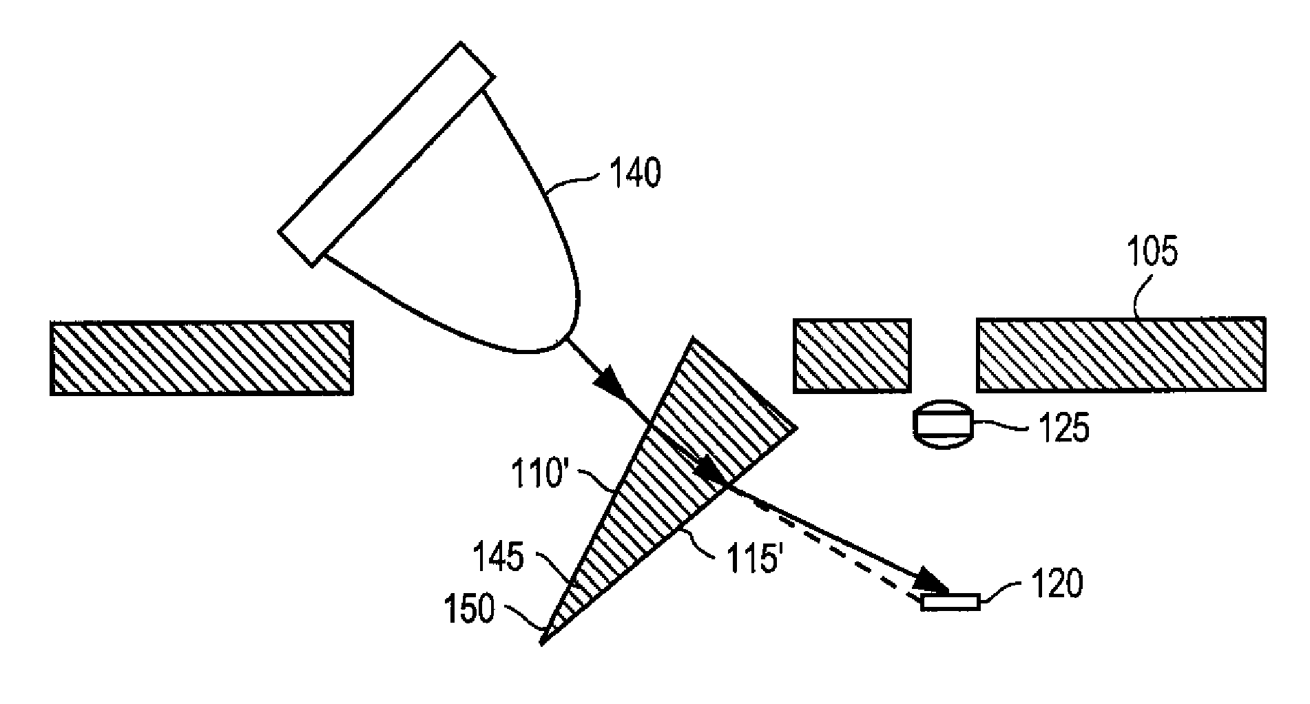
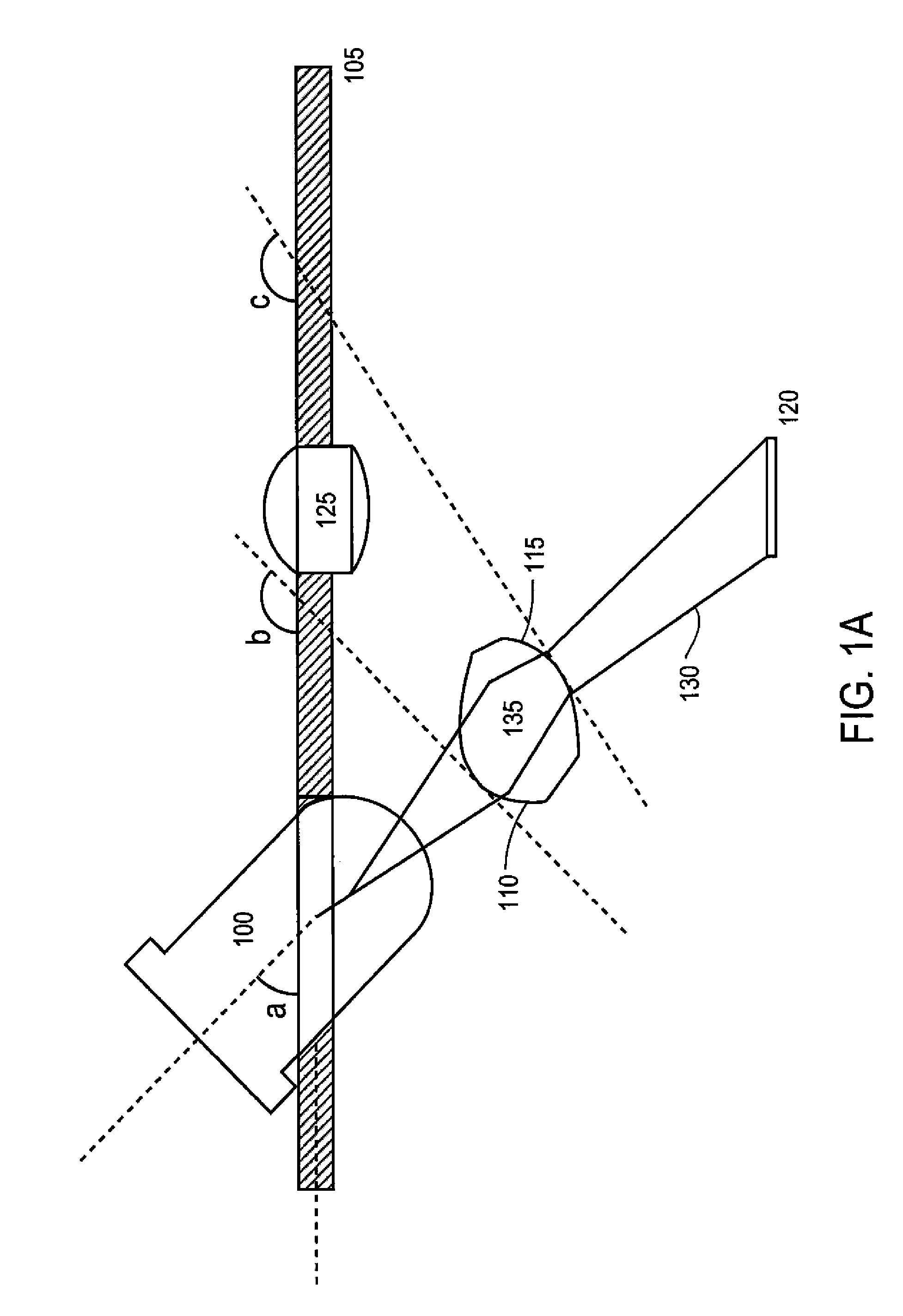
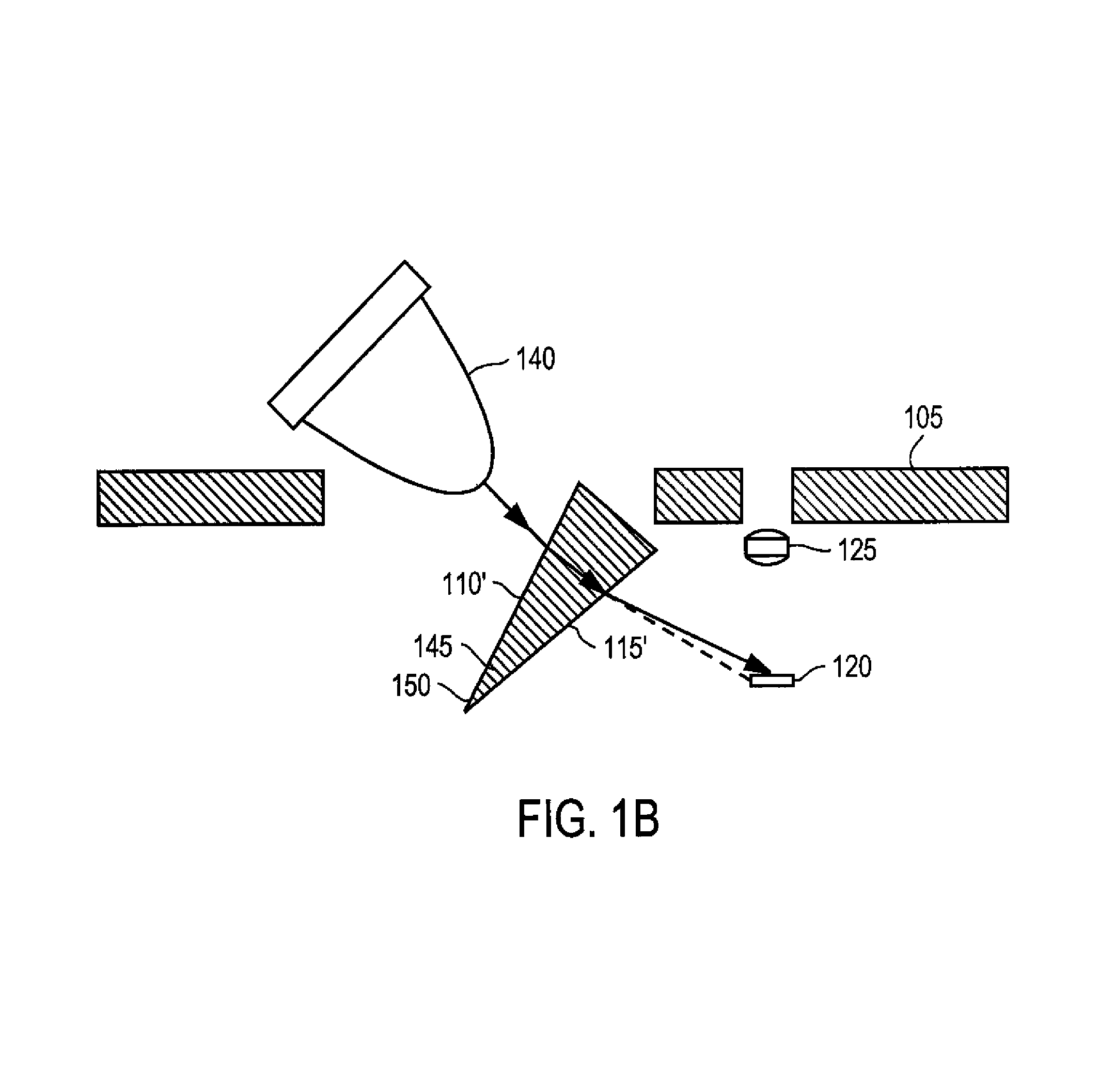
[0024]The following description of the present invention is presented in the context of an optical illumination for optical displacement detection system for use in, for example, a computer input device. In some embodiments, the principles disclosed may be implemented for use in an optical mouse or an optical trackball. One skilled in the art will recognize that the present invention may be implemented in many other domains and environments, both within the context of optical illumination for optical displacement detection, and in other contexts. Different embodiments of the present invention are now described with reference to the figures where like reference numbers indicate identical or functionally similar elements. Also in the figures, the left most digit of each reference number corresponds to the figure in which the reference number is first used.

[0025]Accordingly, the following description, while intended to be illustrative of a particular implementation, is not intended to ...


PUM


Abstract

A system, method, and method of manufacturing directed to an optical device with an efficient optical illumination. The optical illumination can be provided by tilting a light source and using a refractive lens to direct the light onto a surface. Alternatively, the optical illumination can be provided using total internal reflection with a conical light pipe and a curvatured entrance and exit surface.

Description

CROSS REFERENCE TO RELATED APPLICATIONS[0001]The present application claims priority from provisional U.S. Patent Application Ser. No. 60 / 290,268, for “An Optical Illumination System and Method,” filed May 10, 2001, the disclosure of which is incorporated herein by reference.BACKGROUND[0002]A. Technical Field[0003]The present invention relates generally to optical technology, and more particularly, to optical technology in an input device.[0004]B. Background[0005]Optical technology is used in many contexts, including in optical input devices. There are many different types of input devices, including a mouse, a trackball, and a joystick. There are significant advantages to using optical input devices over mechanical and opto-mechanical input devices. For example, mechanical or opto-mechanical input devices have mechanical components that are more susceptible to breakdown or wear out. Optical devices having only solid state components are less susceptible to such breakdown or wear ou...

Claims


Application Information

Patent Timeline
Patent Type & Authority Patents(United States)
IPC IPC(8): G09G5/00G06F3/033G06F3/042
CPCG06F3/0317G06F3/03543
Inventor THEYTAZ, OLIVIERPILLOUD, FRANCISEICHENBERGER, PASCAL
Owner LOGITECH EURO SA
Why Eureka
Try Eureka