
Dichroic mangin mirror

a mirror and dichroic technology, applied in the field of dichroic mangin mirrors, can solve the problems of ineffective design for removing more, longitudinal chromatic aberration, inability of the lens to focus different colors, etc., and achieve the effect of eliminating the chromatic aberration caused by the dispersion and certain degree of monochromatic aberration

Inactive Publication Date: 2008-02-19
NORTHROP GRUMMAN SYST CORP
View PDF7 Cites 6 Cited by
  • Summary
  • Abstract
  • Description
  • Claims
  • Application Information

AI Technical Summary

Benefits of technology

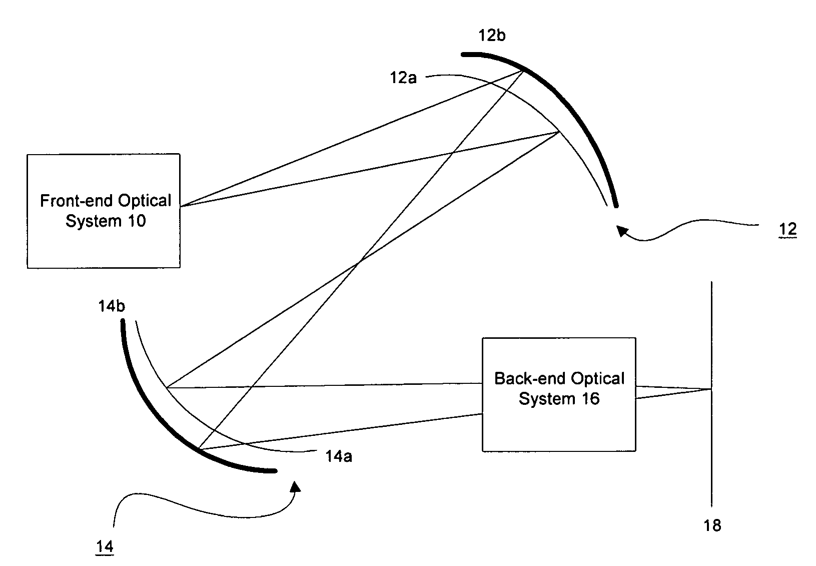
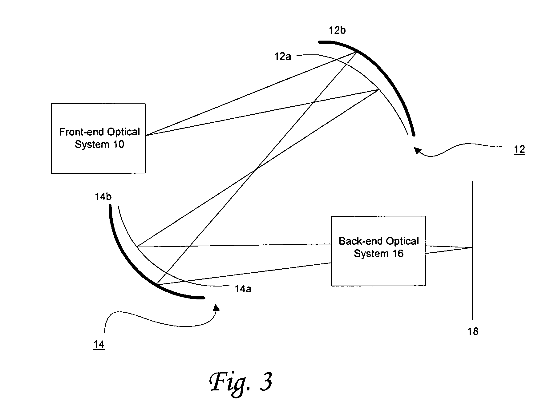
The patent describes an optical system that uses a dichroic Mangin mirror to correct chromatic aberration in an optical beam. The system includes a front-end optical sub-system or a light source that emits an optical beam. The optical beam is then dispersed into two color beams with monochromatic aberration. The dichroic Mangin mirror is placed along the optical paths of both color beams. The mirror has two surfaces, one of which transmits the first color beam and reflects the second color beam, while the other surface reflects the second color beam. This allows the two color beams to be focused at the same position, which is referred to as an achromatic system focus. The geometry of the surfaces can be adjusted to correct the aberration caused by the optical beam. The optical system also includes an achromatic corrector to correct the optical beam in different wavelength ranges. The dichroic Mangin mirror has a first lens portion and a mirror portion, which allows for independent adjustment of the first and second color beams. Overall, the optical system provides improved chromatic accuracy and correction of chromatic aberration in optical beams.

Problems solved by technology

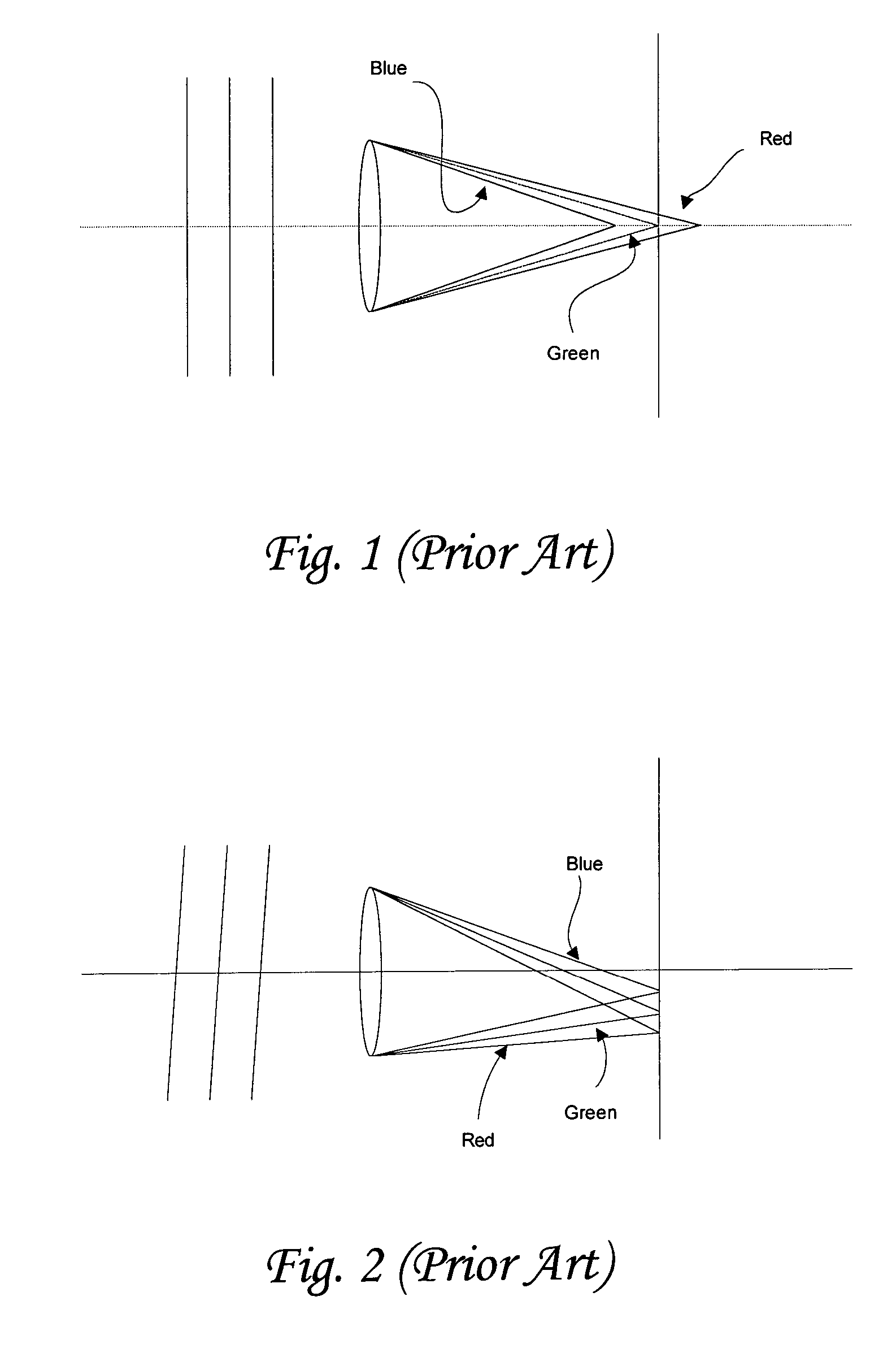
The longitudinal chromatic aberration is the inability of a lens to focus different colors at the same focal point.
However, most of these optical designs, though effective to resolve one of the aberrations, will inevitably cause other adverse optical effects or the design may be ineffective for removing more than one aberration.

Method used


Image

  • Dichroic mangin mirror
  • Dichroic mangin mirror
  • Dichroic mangin mirror

Examples


Embodiment Construction

[0016]Mirrors are widely used in telescopes and telephoto lenses for having the advantage of operating over a wider range of wavelengths, from infrared to ultraviolet and above and ability to avoid chromatic aberration arising from dispersion in lenses. However, mirrors are still subject to other aberrations. Instruments which use only mirrors to form images are called catoptric systems, while those which use both lenses and mirrors are called catadioptric systems (dioptric systems being those with lenses only). The fundamental philosophy behind most catadioptric systems is to use refracting elements to correct the aberrations of a system of spherical mirrors without introducing any new aberrations. An ordinary Mangin mirror is typically a meniscus negative lens having a reflection coating formed on a second surface thereof to provide the effect of a lens plus a mirror. The Mangin mirror has been used to correct spherical aberration and also has a reduced coma contribution, but it i...


PUM


Abstract

An optical system having at least one dichroic Mangin mirror. The optical system has a front-end optical sub-system or a light source operative to emit an optical beam. The optical beam is dispersed into at least a first color beam and a second color beam and has certain degree of monochromatic aberration. The dichroic Mangin mirror is disposed along the optical paths of both the first and second color beams. The dichroic Mangin mirror includes a first surface operative to transmit the first color beam only, but reflects the second color beam. Therefore, upon incident on the dichroic Mangin mirror, the second color beam is reflected, while the first color beam transmits through the first surface and is then reflected off from the second surface. Thereby, the first and second color beams can be focused at the same position, which is referred as an achromatic system focus. Thereby, the chromatic aberration caused by the dispersion can be eliminated.

Description

CROSS-REFERENCE TO RELATED APPLICATIONS[0001]Not ApplicableSTATEMENT RE: FEDERALLY SPONSORED RESEARCH / DEVELOPMENT[0002]Not ApplicableBACKGROUND[0003]The present invention relates in general to a device for correcting chromatic and other types of aberration, and more particularly, to a dichroic Mangin mirror operative to achromatize a large spectrum and correct aberration.[0004]When a light beam composed of multiple wavelengths propagates through a medium, the index of refraction is wavelength dependent. The wavelength dependence is known as dispersion. A well-known dispersion example is a glass prism that disperses an incident beam of white light into a rainbow color. Many optical devices or elements, such as photographic lenses that comprise various dispersive, dielectric glasses, do not refract all constituent wavelengths of an incident light beam at the same angle. This causes the departure of a perfect imaging for a multi-wavelength light beam. For a color light beam, the depart...

Claims


Application Information

Patent Timeline
Patent Type & Authority Patents(United States)
IPC IPC(8): G02B27/14G02B17/00
CPCG02B17/0856G02B27/0025
Inventor JACKSON, JOHN E.
Owner NORTHROP GRUMMAN SYST CORP
Learn More