Electro-optical device and electronic apparatus

Active Publication Date: 2012-08-02
SEIKO EPSON CORP
View PDF15 Cites 1 Cited by
  • Summary
  • Abstract
  • Description
  • Claims
  • Application Information

AI Technical Summary

Benefits of technology

[0008]It is an advantage of some aspects of the invention to improve the brightness of a displayed i

Problems solved by technology

With this scheme, crosstalk, in which the right-eye image and the left-eye image become intermixed, occurs during an interval in which one of the right-eye image and the left-eye image is rewritten by the other side; when a viewer sees the image, it is difficult for him or her to clearly recognize that image as a stereoscopic image.
For this reason, crosstalk cannot be sufficiently suppressed even with the afo

Method used


Image

  • Electro-optical device and electronic apparatus
  • Electro-optical device and electronic apparatus
  • Electro-optical device and electronic apparatus

Examples


first embodiment

1. First Embodiment

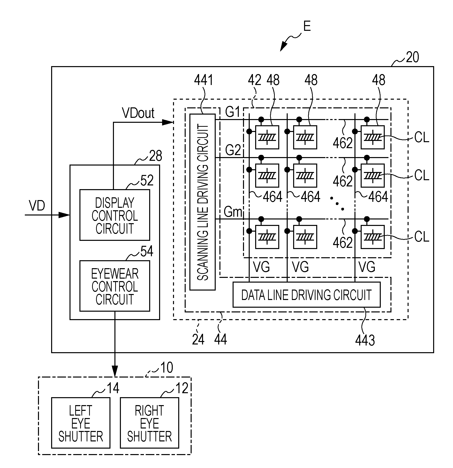
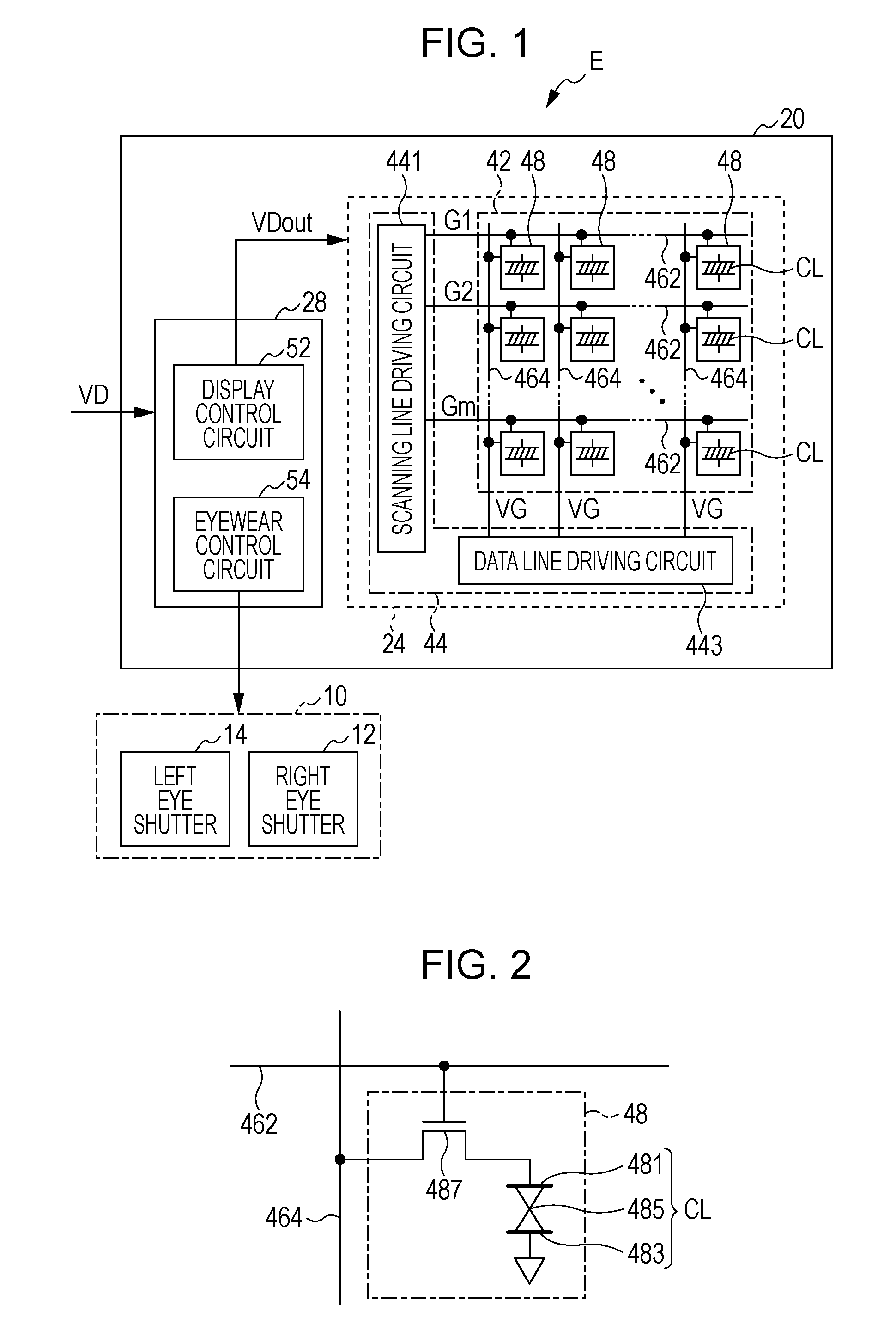
[0034]FIG. 1 is a block diagram illustrating an electronic apparatus E according to a first embodiment of the invention. The electronic apparatus E displays stereoscopic images, which are sensed stereoscopically by a viewer, using a frame-sequential scheme. As shown in FIG. 1, the electronic apparatus E includes stereoscopic eyewear 10 and an electro-optical device 20.

[0035]The stereoscopic eyewear 10 shown in FIG. 1 is an eyeglass-shaped implement donned by a viewer when viewing stereoscopic images displayed by the electro-optical device 20, and is configured so as to include a right-eye shutter 12 located in front of the right eye of the viewer and a left-eye shutter 14 located in front of the left eye of the viewer. The right-eye shutter 12 and the left-eye shutter 14 are controlled so as to take on an open state that allows emitted light to pass through and a closed state that blocks emitted light. For example, liquid-crystal shutters that change from the open...

second embodiment

2. Second Embodiment

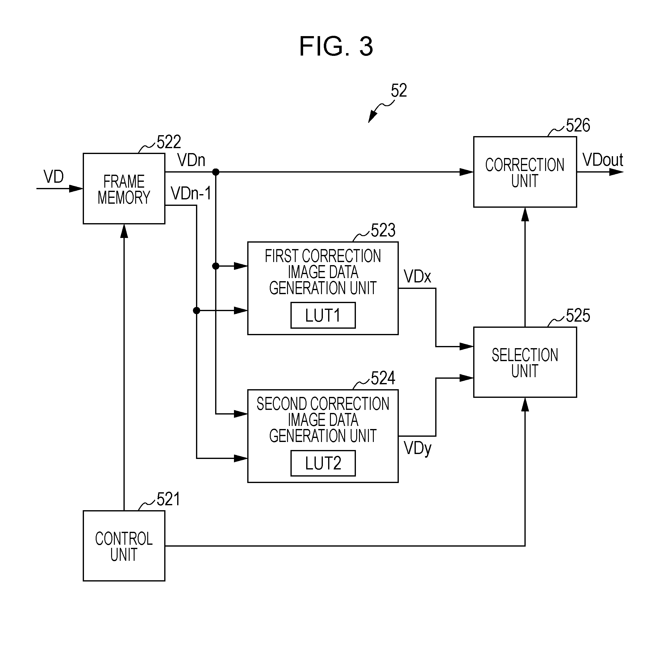
[0058]In the aforementioned first embodiment, the second correction image data generation unit 524 is compliant with a single type of stereoscopic eyewear 10. As opposed to this, the electronic apparatus E according to the second embodiment is compliant with a plurality of types of stereoscopic eyewear 10, and aside from the display control circuit 52 being replaced with a display control circuit 52A as shown in FIG. 8, has the same configuration as the electronic apparatus E according to the first embodiment.

[0059]In the display control circuit 52A, the second correction table LUT 2 includes k (where k is an integer of 2 or more) individual correction tables LUT 21, LUT 22, and so on up to LUT 2k. The k second correction tables LUT 21, LUT 22, and so on up to LUT 2k correspond to each of k types of stereoscopic eyewear 10. An identification signal ID that identifies the type of the stereoscopic eyewear 10 is sent from the stereoscopic eyewear 10. A control unit ...

third embodiment

3. Third Embodiment

[0062]In the aforementioned first embodiment, the second correction image data generation unit 524 includes the second correction table LUT 2, which corresponds to a certain temperature. As opposed to this, an electronic apparatus E according to the third embodiment includes individual correction tables LUT 31, LUT 32, and so on up to LUT 3k, which correspond to a plurality of temperatures.

[0063]FIG. 9 illustrates a display control circuit 52B according to the third embodiment. In the display control circuit 52B, the second correction table LUT 2 includes k (where k is an integer of 2 or more) individual correction tables LUT 31, LUT 32, and so on up to LUT 3k. The k individual correction tables LUT 31, LUT 32, and so on up to LUT 3k correspond to each of k types of temperatures.

[0064]A temperature sensor 527 detects a temperature and supplies a temperature signal indicating the detected temperature to a control unit 521B. The control unit 521B then generates a se...


PUM


Abstract

A display control circuit includes: a frame memory; a first correction image data generation unit that generates first correction image data that corrects a response characteristic of an electro-optical element; a second correction image data generation unit that generates second correction image data that corrects the intermixing of a right-eye image and a left-eye image; a selection unit that selects the first correction image data in a first field and the second correction image data in a second and subsequent fields; and a correction unit that generates output image data by correcting the first image data.

Description

BACKGROUND[0001]1. Technical Field[0002]The present invention relates to techniques for displaying right-eye images and left-eye images that have been made disparate from each other so that a viewer senses a stereoscopic image.[0003]2. Related Art[0004]In the past, a frame-sequential stereoscopic scheme that displays right-eye images and left-eye images alternately through time division has been proposed. With this scheme, crosstalk, in which the right-eye image and the left-eye image become intermixed, occurs during an interval in which one of the right-eye image and the left-eye image is rewritten by the other side; when a viewer sees the image, it is difficult for him or her to clearly recognize that image as a stereoscopic image.[0005]In order to solve this problem, JP-A-2001-54143, for example, discloses a technique in which crosstalk from a left-eye image is corrected in advance when a right-eye image is displayed and crosstalk from a right-eye image is corrected in advance wh...

Claims


Application Information

Patent Timeline
IPC IPC(8): H04N13/04
CPCG02B27/2228G02B27/2264H04N13/0497H04N13/0033H04N13/0438H04N13/0018G02B30/24G02B30/34H04N13/122H04N13/144H04N13/341H04N13/398
Inventor YOSHIMOTO, HIROSHI
Owner SEIKO EPSON CORP
Why Eureka
Try Eureka