Isolating type self-oscillating flyback converter with a soft start loop

a converter and self-oscillating technology, applied in the direction of dc-dc conversion, power conversion systems, instruments, etc., can solve the problems of bad product start problem and circuit will generate flyback, and achieve the effect of improving the start feature of the circui

Inactive Publication Date: 2008-02-19
MORNSUN GUANGZHOU SCI & TECH
View PDF10 Cites 17 Cited by
  • Summary
  • Abstract
  • Description
  • Claims
  • Application Information

AI Technical Summary

Benefits of technology

[0004]The purpose of this invention is to provide an isolating type self-oscillating flyback converter, which has small start current and can work normally when the input voltage becomes high.
[0008]Comparing with the prior all, the present invention has the following advantages: 1. the start current of the circuit is quite small because of the soft start loop added in, and no matter whether the load is a high load or a capacitor load, only very small start current will be generated, thus improving the start feature of the circuit; 2. there is no requirement for the input voltage, and the circuit can work normally when the input voltage is high.

Problems solved by technology

After start-up of self-oscillation, the circuit will generate flyback.
In addition, when the input voltage is high and at the moment that the voltage is just applied, there will appear a very high instantaneous current spike on the resistors R1 and R2, which makes the transistor momentarily become conductive, and the current spike of this moment may strike through the transistor; meanwhile, the high voltage applied on the transistor may cause damage to the transistor, and therefore cause the bad start problem of the product.

Method used


Image

  • Isolating type self-oscillating flyback converter with a soft start loop
  • Isolating type self-oscillating flyback converter with a soft start loop
  • Isolating type self-oscillating flyback converter with a soft start loop

Examples


Embodiment Construction

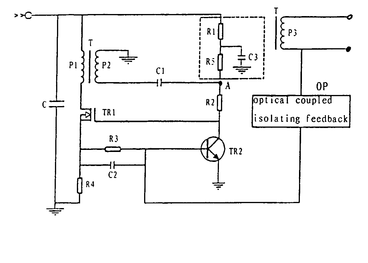
[0012]As shown in FIG. 2, the first embodiment of the present invention includes a coupled transformer T, a FET TR1, an oscillating transistor TR2 and an electro-optical coupled isolating feedback unit OP; wherein the input terminal of the circuit is connected to the source of the FET TR1 through a primary winding P1 of the coupled transformer T; the input terminal of the circuit is connected to the collector of the transistor TR2 through resistors R1 and R2; the source of the FET TR1 is connected to the collector of the transistor TR2; one branch of the drain of the FET TR1 is connected to the ground through a resistor R4, and the other branch is connected to the base of the transistor TR2 through the parallel connection unit of the resistor R3 and the capacitor C2; the base of the transistor TR2 is connected to the output terminal of a secondary output winding P3 of the coupled transformer T through the electro-optical coupled isolating feedback unit; the series connection joint A...


PUM


Abstract

An isolating type self-oscillating flyback converter is disclosed, which includes a coupled transformer, a FET, a transistor and an electro-optical coupled isolating feedback unit, wherein the input terminal of the circuit is connected to the source of the FET through a primary winding of the coupled transformer, the input terminal of the circuit is connected to the collector of the transistor through a resistor R1 and another resistor R2, the source of the FET is connected to the collector of the transistor, one branch of the drain of the FET is connected to the ground through a resistor, while the other branch is connected to the base of the transistor through the parallel connection body of a resistor and a capacitor, the base of the transistor is connected to the output terminal of a secondary output winding of the coupled transformer through the electro-optical coupled isolating feedback unit; the series connection joint between the said resistor R1 and the said resistor R2 is connected to the ground through a speedup capacitor and a secondary winding of the coupled transformer; a loop for implementing the soft start is connected between the said input terminal of the circuit and the series connection joint. Thus the start current of the invention is small and the converter can keep working normally when the input voltage is high.

Description

BACKGROUND OF THE INVENTION[0001]The present invention relates to an isolating type self-oscillating flyback converter used in a self-oscillating flyback power module.[0002]A conventional isolating type self-oscillating flyback converter includes a coupled transformer, a FET (Field-Effect Transistor), an oscillating transistor and an electro-optical coupled isolating unit. As shown in FIG. 1, after applying voltage to the input terminal, the current directly flows through resistors R1 and R2 to make the FET TR1 tend to be conductive. When there is a current flowing through the primary winding P1 of the coupled transformer, the polarity of the secondary winding P2 produced by the coupling effect makes the conductivity of the FET TR1 increase further. The positive voltage of the secondary winding P2 is initially transmitted to the FET TR1 through a speedup capacitor C1 and a resistor R2, therefore, the front edge of the waveform of the driving current is very steep, which facilitates ...

Claims


Application Information

Patent Timeline
Patent Type & Authority Patents(United States)
IPC IPC(8): H02M7/5375H02M3/338
CPCH02M3/3381
Inventor YIN, XIANGYANG
Owner MORNSUN GUANGZHOU SCI & TECH
Why Eureka
Try Eureka