Buckle

a technology of buckle and handle, which is applied in the field of buckle, can solve the problems of wasting a lot of energy to heat and melt such zinc-aluminum alloy, affecting the service life of the buckle, etc., and achieves the effect of reducing the cost of repairing and maintaining the buckle, reducing the buckle, and improving the service li

Inactive Publication Date: 2008-02-26
HUANG HAN CHING
View PDF3 Cites 24 Cited by
  • Summary
  • Abstract
  • Description
  • Claims
  • Application Information

AI Technical Summary

Benefits of technology

[0011]According to the present invention, a buckle includes a base made by pressing and formed with two walls, a cross member between the walls and a jaw between the walls. A jaw is made by rolling and formed with a cam, two non-circular blocks extending from the cam and two shafts extending from the non-circular blocks into an aperture defined in each of the walls of the base. A handle is made by pressing and formed with a touch portion and two non-circular braces for holding the non-circular blocks of the jaw. A handle is installed on the base so that a gap is defined between the jaw of the base and the jaw of the handle. The handle can be pivoted on the base between a first position where the gap is small and a second position where the gap is large. An elastic element tends to keep the handle in the first position.
[0013]Another advantage of the buckle according to the present invention is the use of a small amount of material.
[0014]Another advantage of the buckle according to the present invention is to provide a compact and light structure.
[0015]Another advantage of the buckle according to the present invention is firm clamping of the strap due to the use of the jaws biased by the elastic element.

Problems solved by technology

Furthermore, such zinc-aluminum alloy is soft so that the rigidity of both of the base 2 and the handle 3 is inadequate.
Moreover, a lot of energy is consumed to heat and melt such zinc-aluminum alloy.
In addition, it takes a long period of time for the base 2 and the handle 3 to cool down before they can be subject to finishing.
Furthermore, it costs a lot of money to develop molds for molding the base 2 and the handle 3.

Method used


Image

  • Buckle
  • Buckle
  • Buckle

Examples


first embodiment

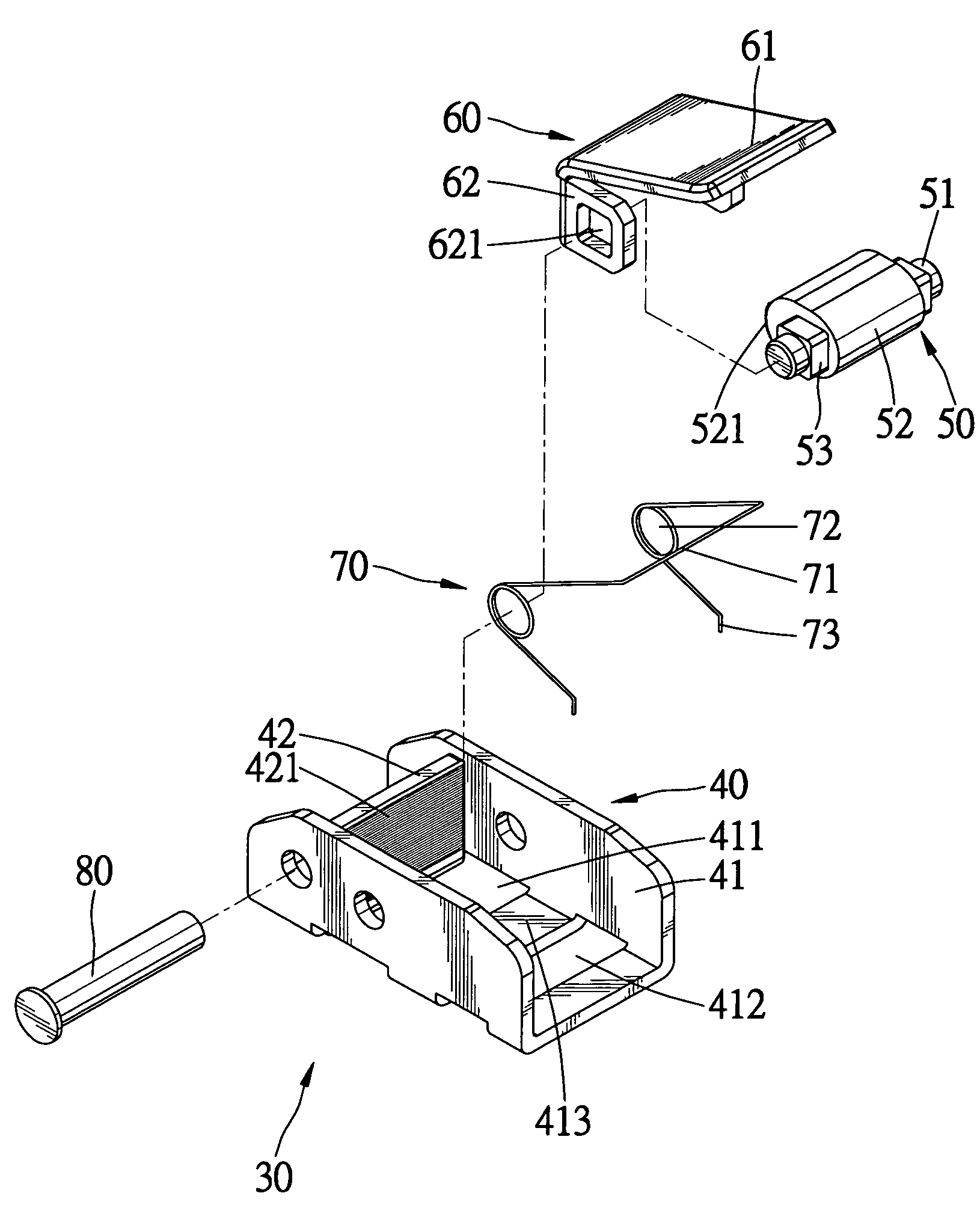
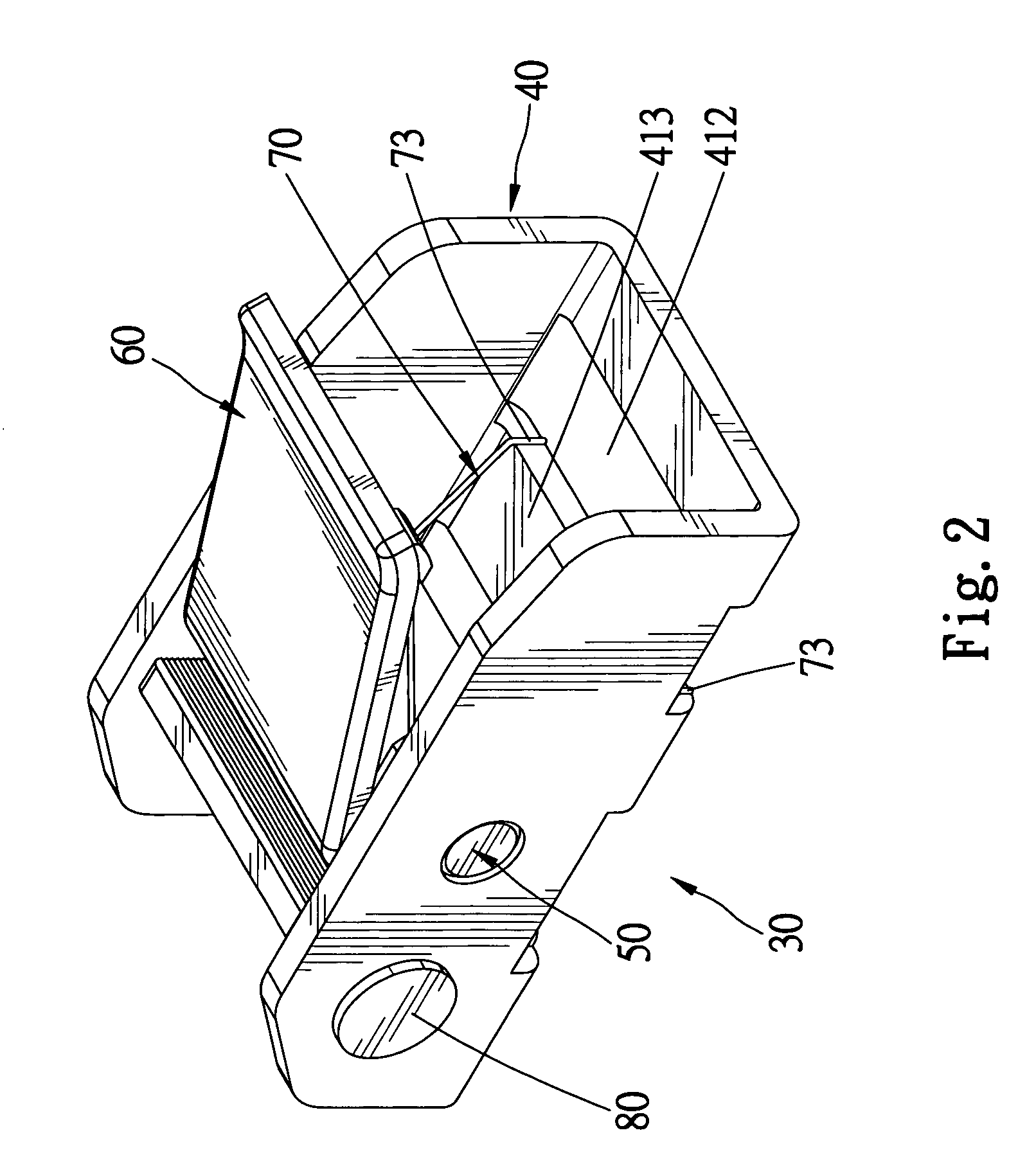
[0027]FIGS. 2 and 3 shows a buckle 30 according to the present invention. The buckle 30 includes a base 40, a jaw 50, a handle 60 and an elastic element 70. The base 40 and the handle 60 are made of iron in a continuous pressing or punching process with ease at a low cost. The jaw 50 is made of iron in a rolling process with ease at a low cost.

[0028]The base 40 is made of a first iron sheet including a middle portion and two lateral portions. In the continuous pressing process, the lateral portions of the first iron sheet are bent from the middle portion of the first iron sheet so that the former extend perpendicular to the latter. The lateral portions of the first iron sheet become walls 41 while the middle lateral portion of the same becomes a floor. Hence, the base 40 is U-shaped in an end-view.

[0029]The floor is punched so that a portion thereof is removed, leaving an opening 412 therein and that a portion 42 thereof is bent, leaving an opening 411 therein. The opening 411 is se...

second embodiment

[0039]Referring to FIGS. 6 through 9, there is shown a buckle 90 according to the present invention. The buckle 90 includes a base 100, a jaw 50, a handle 60 and an elastic element 70. The base 100 and the handle 60 are made of iron in a continuous pressing or punching process.

[0040]The base 100 is made of an iron plate. The base 100 includes two walls 101, a cross member 104 extending between the walls 101, a jaw 102 extending between the walls 101 and an opening 103 for separating the cross member 104 from the jaw 102. The jaw 102 and the cross member 104 extend in a same plane. The jaw 102 is formed with a plurality of teeth 105. A rivet 120 is fit in an aperture defined in each of the walls 101 of the base 100 for reinforcing the base 100. Each shaft 51 of the jaw 50 is inserted in an aperture 110 defined in one of the walls 101 of the base 100 and through one of the helical portions 72 of the elastic element 70 so that the base 100, the jaw 50, the handle 60 and the elastic ele...


PUM


Abstract

A buckle includes a base made by pressing and formed with two walls, a cross member between the walls and a jaw between the walls. A jaw is made by rolling and formed with a cam, two non-circular blocks extending from the cam and two shafts extending from the non-circular blocks into an aperture defined in each of the walls of the base. A handle is made by pressing and formed with a touch portion and two non-circular braces for holding the non-circular blocks of the jaw. A handle is installed on the base so that a gap is defined between the jaw of the base and the jaw of the handle. The handle can be pivoted on the base between a first position where the gap is small and a second position where the gap is large. An elastic element tends to keep the handle in the first position.

Description

BACKGROUND OF INVENTION[0001]1. Field of Invention[0002]The present invention relates to a buckle and, more particularly, to a buckle that is manufactured with ease at a low cost.[0003]2. Related Prior Art[0004]Referring to FIG. 1, a conventional buckle 1 includes a handle 3 pivotally installed on a base 2. The base 2 includes two walls 11, a cross member 10 formed between the walls 11 and a jaw 12 formed between the walls 11. The jaw 12 is perpendicular to the cross member 10. The jaw 12 is formed with a plurality of teeth 13 on a side. A bar 6 is fit in an aperture defied in each of the walls 11 for supporting the jaw 12. The base 2 defines two openings 8 and 9 separated by the cross member 10.[0005]The handle 3 includes a cam 14 and a touch portion 17 extending from the cam 14. The cam 14 is formed with a plurality of teeth 15. A tunnel 16 is defined in the cam 14.[0006]An elastic element 5 includes a middle portion 18 and two lateral portions. Each of the lateral portions of the...

Claims


Application Information

Patent Timeline
Patent Type & Authority Patents(United States)
IPC IPC(8): A44B11/12
CPCB60P7/0823Y10T24/2175Y10T24/4016
Inventor HUANG, HAN-CHING
Owner HUANG HAN CHING
Why Eureka
Try Eureka