Fuel injector and in-cylinder direct-injection gasoline engine

a fuel injector and gasoline engine technology, which is applied in the direction of fuel injection apparatus, combustion engines, feed systems, etc., can solve the problems of not getting better atomization performance, and achieve the effect of enhancing atomization, fuel flow rate, and not significantly decreasing the outer periphery

Inactive Publication Date: 2008-02-26
HITACHI LTD
View PDF14 Cites 16 Cited by
  • Summary
  • Abstract
  • Description
  • Claims
  • Application Information

AI Technical Summary

Benefits of technology

[0013]To increase the fuel economy and exhaustion performance of an in-cylinder injection engine, it is important to improve the atomization property and perform optimum spray pattern control.
[0014]It is an object of the present invention to improve atomization performance of a fuel injector and to provide a fuel injector that enables adjustment of a spray pattern to obtain sprays preferable for an engine.
[0021]Specifically, a fuel inlet hole having a tapered diameter is formed in the fuel path extending from the seat portion of the fuel injector to the plurality of nozzle holes, an orifice plate in a concave shape is provided downstream of the fuel inlet hole, and a plurality of nozzle holes are formed concentrically at the concave bottom of the orifice plate toward the outside. After the fuel flow toward the nozzle holes collides against the central part of the concave bottom, the fuel flows radially and reaches the respective nozzle holes. Since the radial paths are tapered, the fuel flow rates at the outer periphery do not decrease significantly. Accordingly, high-speed fuel flows are achieved, enhancing atomization. The nozzle holes formed concentrically make the fuel flow rates homogeneous, resulting in superior atomization in each hole. Since the orifice plate has a concave shape which enables the mechanical strength to be increased, the injection fuel is highly pressurized. This further increases the fuel flow rate, thereby further enhancing atomization.
[0022]Each of the plurality of nozzle holes formed concentrically at the concave bottom of the orifice plate toward the outside has a desired inclined angle inside the concave bottom surface and in the direction of the plate thickness, which enables adjustment of a spray pattern. Particularly, interaction of the spray flows from the individual nozzle holes can be used; when, for example, the nozzle holes are formed close to one another, the surrounding air is suppressed from being introduced and the distance by which the spray travels can be controlled. Conversely, when the nozzle holes are spaced apart from one another, the sprays can be oriented in desired directions by avoiding their interference so as to create substantially flat sprays. This enables injection even in a flat combustion chamber.
[0023]A fuel injector according to the present invention forms sprays preferable for an engine by improving atomization performance of the fuel injector and enabling adjustment of a spray pattern.

Problems solved by technology

In the prior arts described in Patent Documents 1 to 3, the entire nozzle front chamber is flat so that the fuel flow from the outer periphery toward the inner periphery and subsequent collisions immediately above the nozzle holes allow dispersion to be caused easily to enhance atomization; the structure is not necessarily preferable to further increase the fuel flow rate in the nozzle holes (to, for example, further increase the pressure), and better atomization performance may not be obtained.

Method used


Image

  • Fuel injector and in-cylinder direct-injection gasoline engine
  • Fuel injector and in-cylinder direct-injection gasoline engine
  • Fuel injector and in-cylinder direct-injection gasoline engine

Examples


embodiment 1

[0037]Embodiments of a fuel injector according to the present invention will be now described.

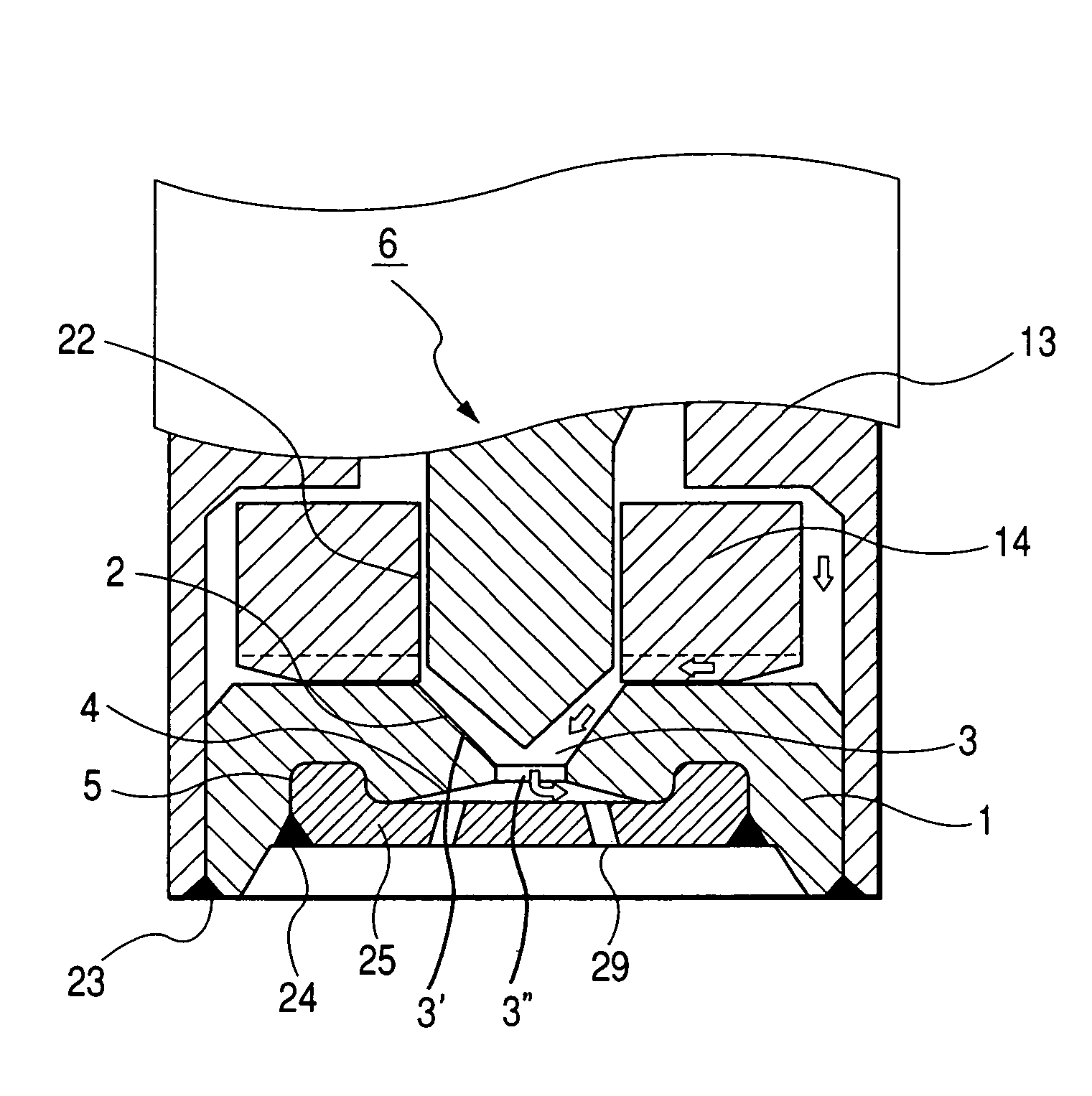
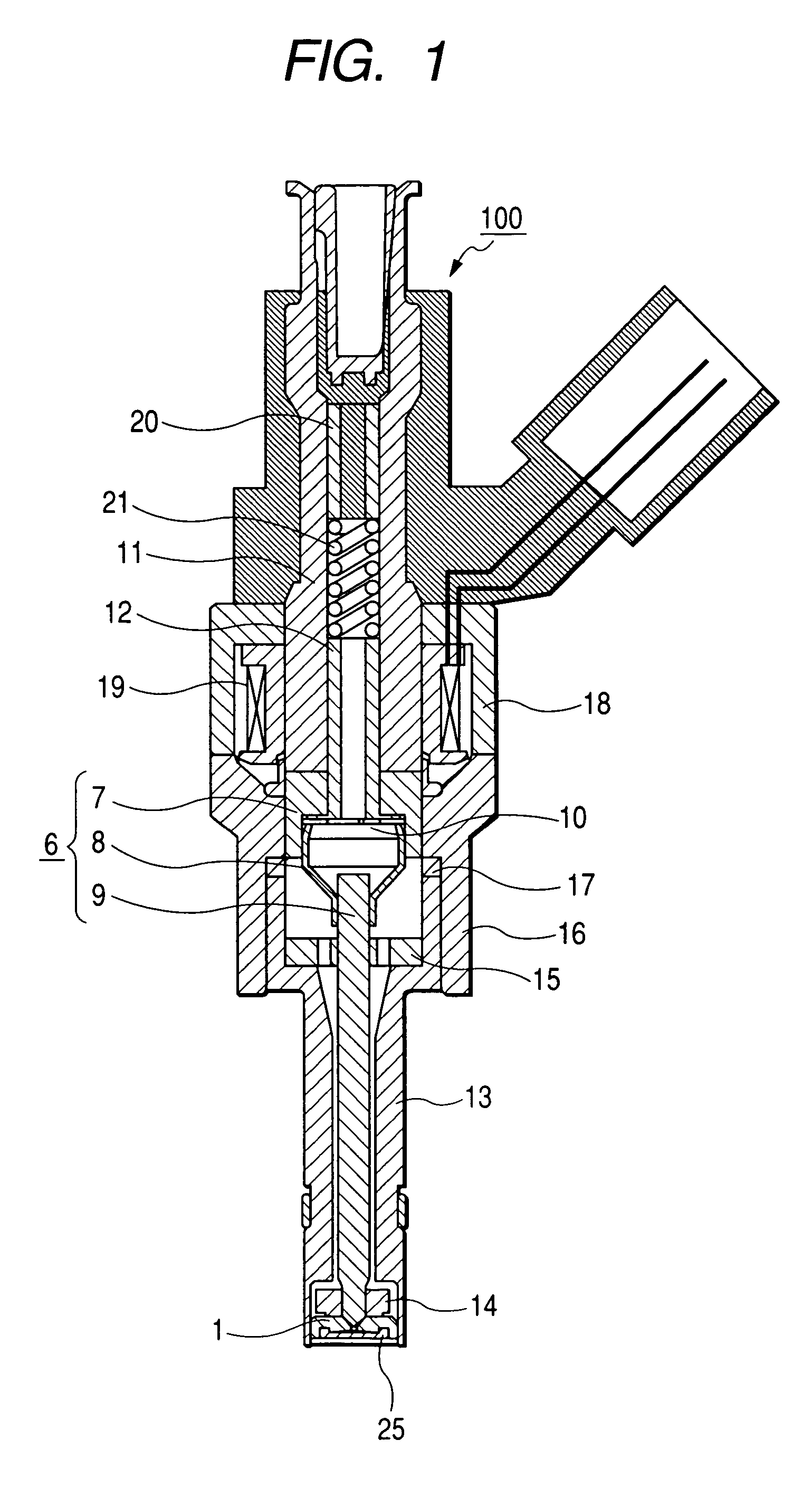
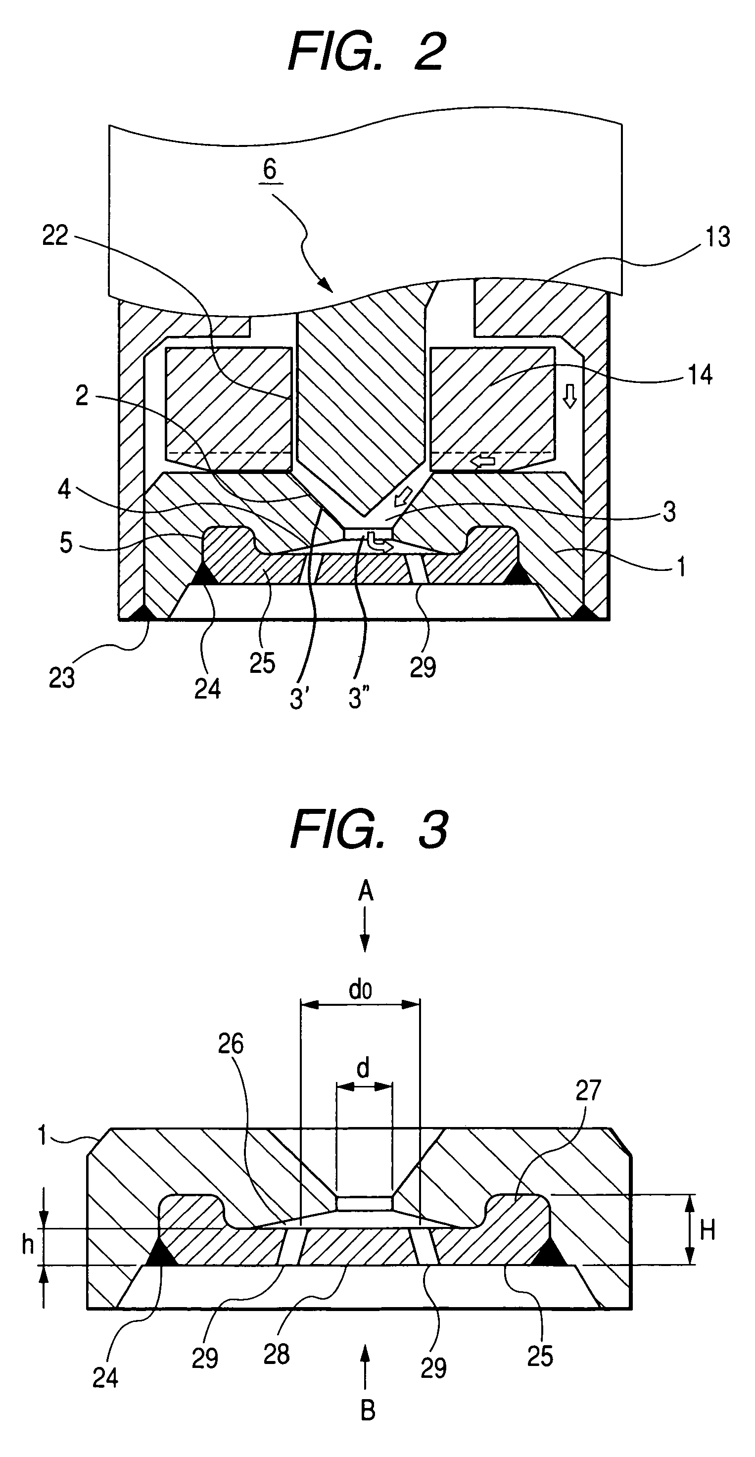
[0038]FIGS. 1 and 2 show a first embodiment of a fuel injector 100. FIG. 1 is a cross-sectional view of the entire structure of the fuel injector 100. FIG. 2 is a local-sectional view of the fuel injector 100 shown in FIG. 1.

[0039]In FIG. 1, a body of the fuel injector 100 is mainly comprised of a nozzle body 13, a nozzle housing 16 for holding the nozzle body 13, a yoke 18 being arranged around an electromagnet 19, and a stationary core 11 etc. A tip side (a lower end portion in FIG. 1) of the nozzle body 13 is provided with a fuel path member 14 and a nozzle plate 1. The fuel path member is shaped like a ring, an inner surface 22 thereof serves as guide for plunger (valve plug) 6-movement. The nozzle plate 1 is provided with a nozzle hole which serves as a nozzle inlet hole 3 in the center thereof. An outer periphery of the nozzle plate 1 is fixed to the nozzle body 13 by welding 23 or an...

embodiment 2

[0082]FIGS. 6 and 7 show the second embodiment of the present invention in which a substantially flat spray pattern is used as an example.

[0083]FIG. 6 shows the arrangement of nozzle holes 41 formed in an orifice plate 40. The other arrangement of the fuel injection is the same as the first embodiment.

[0084]FIG. 7 schematically shows sprays 43 that are obtained by the nozzle holes 41 formed in the orifice plate 40 shown in FIG. 6.

[0085]In FIG. 6, the nozzle holes 41a, 41b, and 41c are concentrically disposed and corresponding holes 42a, 42b, and 42c are formed at the outlet of the nozzle holes at angles directed to desired inclined-directions. This embodiment differs from embodiment 1 shown in FIG. 4 in that the holes 42a are inclined toward the outside so that they do not interfere with each other. Specifically, in FIG. 6 (b), the holes 42a are inclined by about 10 degrees relative to the X axis and by about 40 degrees in the plate thickness direction. Similarly, the holes 42b are ...

embodiment 3

[0088]FIG. 8 shows the third embodiment of the present invention in which flat sprays having a concentration distribution are used as an example. FIG. 8 is a schematic cross-sectional view of sprays 53. The sprays 53 are formed by modifying the layout and inclination of the nozzle holes 29 of the previously mentioned embodiments.

[0089]In FIG. 8, the concentrations of the sprays 53a, 53c, and 53b are reduced gradually in that order. In order to form these sprays, the nozzle holes have the same diameters but have different shapes. As exemplary hole shapes, the holes 29a for the sprays 53a are strait holes, the hole 29c for the sprays 53c are extended holes with a desired spread area from the inlet toward the outlet thereof, and the hole 29b for the spray 53b are also extended holes with a further wider spread area from the inlet toward the outlet thereof. Therefore, the spreads of the sprays become large in succession. Atomization is also enhanced in succession, and thus the travel di...


PUM


Abstract

A fuel injector has a plunger for opening / closing a fuel path to control the amount of fuel to be injected; a seat portion for the plunger; and a plurality of nozzle holes for injecting fuel passed through between the plunger and the seat portion, A nozzle plate is provided with the seat portion, and a taper-fuel inlet hole has a diameter that gradually reduces from the seat toward its outlet, An orifice plate is arranged downstream from the taper-fuel inlet hole, and is provided with a concave portion opposite to the nozzle plate, with a plurality of nozzle holes being formed concentrically at a bottom of the concave portion. Each nozzle hole has an inclined angle in the direction of the plate thickness within the concave area.

Description

CLAIM OF PRIORITTY[0001]The present application claims priority from Japanese application Ser. No. 2005-025307, filed on Feb. 1, 2005, the content of which is hereby incorporated by reference into this application.BACKGROUND OF THE INVENTION[0002]The present invention relates to a fuel injector used in an internal-combustion engine.[0003]With regard to fuel injectors used in internal-combustion engines, a conventional method of injecting fuel from a plurality of nozzle holes is proposed to enhance injection pattern control and atomization (as described in, for example, Patent Document 1: Japanese Application Patent Laid-open Publication No. 2003-314411 (pages 5 and 6, FIG. 1). The fuel injection nozzle described in Patent Document 1 has a nozzle front chamber, which is flat overall. So fuel flows horizontally from the outer periphery side toward the inner periphery side and isotropically collides immediately above the nozzle holes, thereby encouraging dispersion at the time of injec...

Claims


Application Information

Patent Timeline
Patent Type & Authority Patents(United States)
IPC IPC(8): F02B3/02F02M61/18
CPCF02M61/162F02M61/1853
Inventor MIFUJI, MASANORIISHIKAWA, TOHRUSEKINE, ATSUSHIOKAMOTO, YOSHIO
Owner HITACHI LTD
Why Eureka
Try Eureka