
Sensorless start-up method for driving a brushless DC motor

a brushless dc motor and sensorless technology, applied in the direction of motor/generator/converter stopper, electronic commutator, dynamo-electric converter control, etc., can solve the problems of inability to start the process, and inability to detect the position of the rotor, etc., to achieve the effect of low cost and simple steps

Active Publication Date: 2008-02-26
GLOBAL MIXED MODE TECH
View PDF7 Cites 51 Cited by
  • Summary
  • Abstract
  • Description
  • Claims
  • Application Information

AI Technical Summary

Benefits of technology

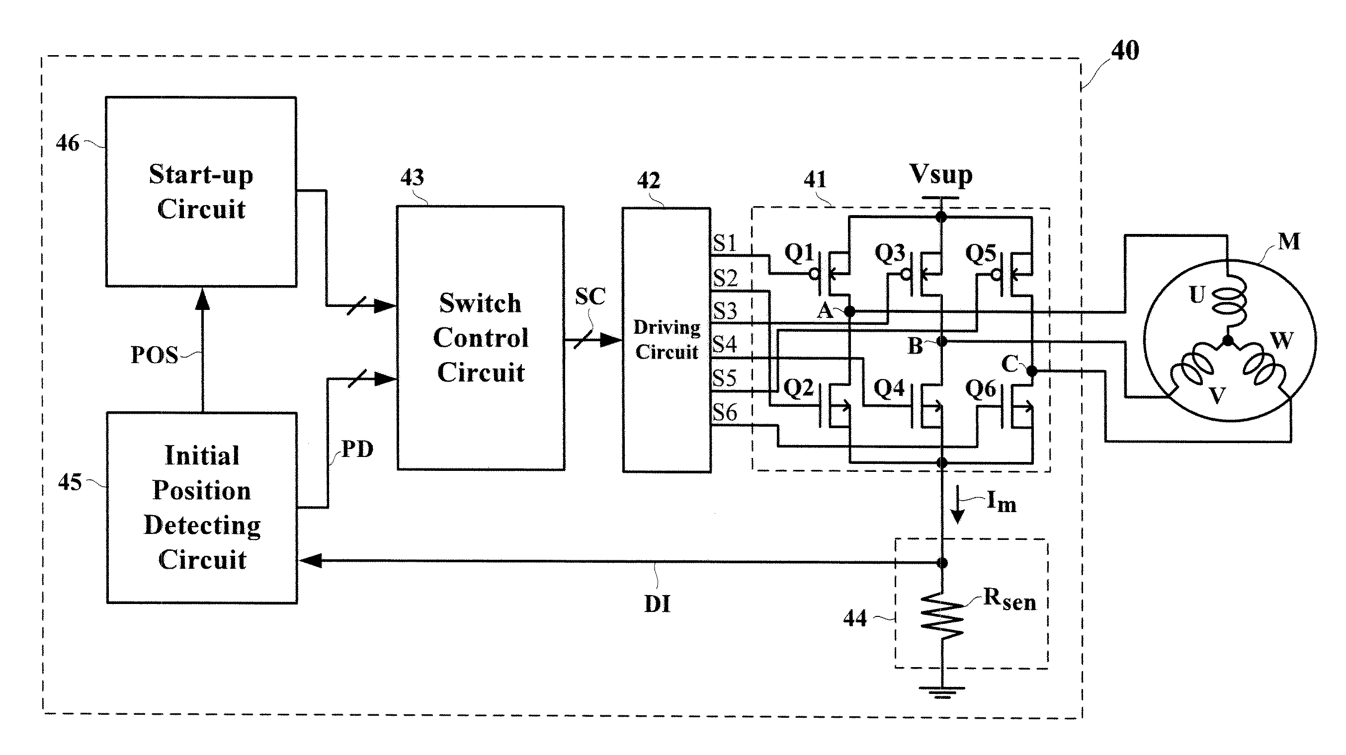
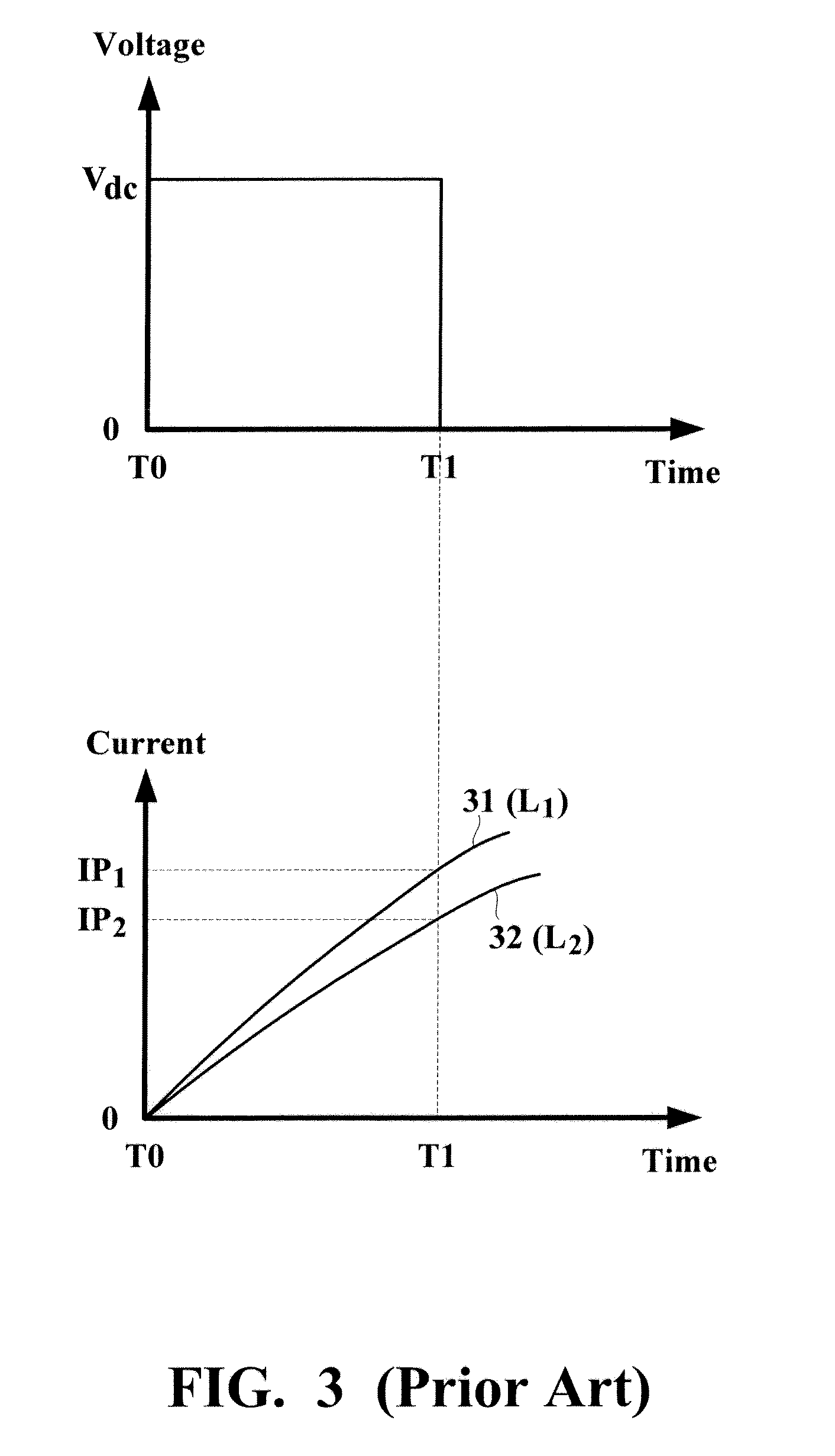
"The present invention provides a sensorless start-up method for driving a brushless motor, which uses simple steps with a low cost by detecting the rotor's initial position in accordance with peak values of motor currents, without the requirement of positional sensors and complicated algorithms. The method detects the rotor's position before starting of the motor, i.e., the rotor is prevented from rotating during the detection period. The method overcomes the failure of start-up and reverse rotation occurred in the conventional methods. The initial position detection phase includes three steps, and the direction of the composite magnetic field generated by the detection mode which generates the largest one of the peak values of the motor currents is determined as the rotor's initial position."

Problems solved by technology

However, the Hall sensors tend to be influenced by the operational environment, which adversely reduces the accuracy of detection.
However, BEMF becomes almost zero when the rotor is static or at a very low rate of rotation, resulting in the impossibility of detecting the rotor's position.
Therefore, one of the most important issues is how to accurately and stably start driving the motor by the sensorless method.
However, the start-up process may fail since the largest torque may not be generated upon the start-up due to the lack of knowledge about the rotor's position.
Nonetheless, the energization of the stator's coils may cause the rotor to reversely rotate, causing limitations to the applicable range.
Unfortunately, these techniques require either complicated algorithms or the feedback of tri-phase voltages and currents.
However, it is difficult to retrieve the common-terminal voltage because the common terminal of the stator's coils is not qualified as a standard input / output interface of the motor structure.

Method used


Image

  • Sensorless start-up method for driving a brushless DC motor
  • Sensorless start-up method for driving a brushless DC motor
  • Sensorless start-up method for driving a brushless DC motor

Examples


Embodiment Construction

[0021]The preferred embodiments according to the present invention will be described in detail with reference to the drawings.

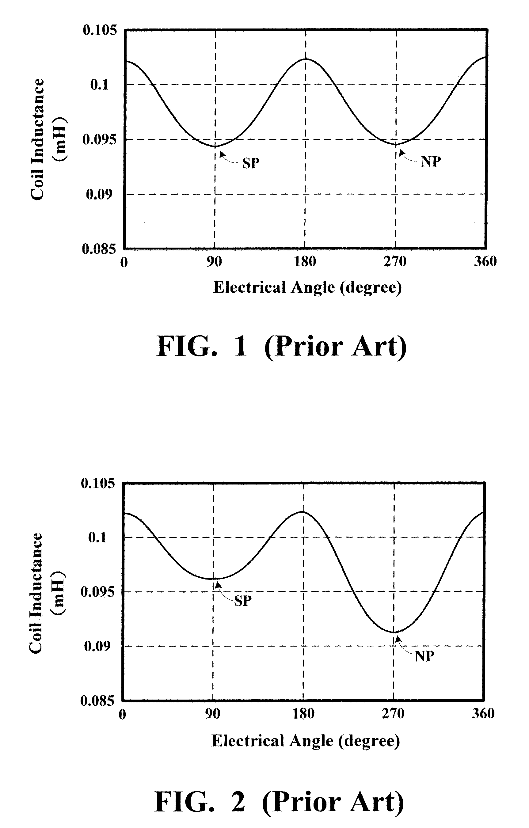
[0022]In a permanent magnet brushless DC motor, a rotor is made of a permanent magnet and a stator is made of coils. Subjected to the influence of magnetic poles of the permanent magnet, the inductance of the stator's coil is not fixed, but a function of an electrical angle of the rotor. FIG. 1 is a chart showing a functional relationship between the coil inductance and the rotor's electrical angle when the motor current is zero. When the coil is aligned in parallel with either the north pole (NP) or the south pole (SP) of the permanent magnet, the coil is subjected to magnetic saturation, causing a reduction of the coil inductance.

[0023]As soon as a current flows through the coil, a magnetic field is induced by the coil. In this case, the functional relationship between the coil inductance and the rotor's electrical angle is affected due to the magnetic inte...


PUM


Abstract

At first, a plurality of detection modes are applied in sequence to a brushless DC motor, such that with respect to each of the detection modes a composite magnetic field generated by a motor current flowing through motor coils points in a different direction. Then, each of peak values of the motor currents generated by the detection modes is compared with respect to one another so as to select, from the plurality of detection modes, one detection mode which generates a largest one of the peak values of the motor currents. An initial position of a rotor is determined on a basis of a direction of a composite magnetic field generated by the detection mode which generates the largest one of the peak values of the motor currents. Based on the initial position of the rotor, the brushless DC motor is driven to start rotating.

Description

BACKGROUND OF THE INVENTION[0001]1. Field of the Invention[0002]The present invention relates to a sensorless start-up method for driving a brushless DC motor.[0003]2. Description of the Related Art[0004]Along with the advancement of technology, motors play a more and more important role in everybody's daily life, such as spindle motors of disc players, drive motors of image scanners, motors in toys, and motors of windscreen wipers. Due to the lack of commutating brushes, permanent magnet brushless DC motors is easier to be taken care of and has a smaller size, a higher efficiency, and other advantages, all of which render the brushless DC motors widely applied in many areas.[0005]A conventional method for driving the permanent magnet brushless DC motor is to detect the position and rotating rate of a rotor through the use of Hall sensors in order to effectively perform the control on the position and rotating rate. However, the Hall sensors tend to be influenced by the operational ...

Claims


Application Information

Patent Timeline
Patent Type & Authority Patents(United States)
IPC IPC(8): H02P6/18
CPCH02P6/20
Inventor CHANG, YEN-CHUANTZOU, YING-YU
Owner GLOBAL MIXED MODE TECH
Learn More