Shroud with aero-effective cooling

a technology of shrouds and cooling passages, which is applied in the direction of machines/engines, stators, liquid fuel engines, etc., can solve the problems of reducing the overall momentum of hot gas flow and the efficiency of turbine blade rotation, so as to improve the efficiency of the engine, reduce drag, and reduce momentum energy loss

Active Publication Date: 2008-02-26
RTX CORP
View PDF9 Cites 27 Cited by
  • Summary
  • Abstract
  • Description
  • Claims
  • Application Information

AI Technical Summary

Benefits of technology

[0007]A turbine shroud section according to the present invention includes a cooling passage that bleeds cooling air into a hot gas flow through an engine. The cooling passage is angled circumferentially to align with a circumferential component of the hot gas flow to reduce momentum energy loss of the hot gas flow and improve the efficiency of the engine.
[0008]In one example, the turbine shroud section includes an airfoil-shaped opening to reduce drag on cooling air bled through the cooling passages.
[0009]A method of cooling a turbine shroud section according to the present invention includes the steps of defining an expected circumferential fluid flow direction adjacent to a turbine shroud. Coolant discharges from a cooling passage in a direction that is substantially aligned with the expected circumferential fluid flow direction. This provides cooling to the shroud section and reduces momentum loss of the fluid flow.

Problems solved by technology

Disadvantageously, axial momentum of the discharged cooling air acts against circumferential momentum of the hot gas flow to undesirably reduce the overall momentum of the hot gas flow.
This results in an aerodynamic disadvantage that reduces efficiency of turbine blade rotation.

Method used


Image

  • Shroud with aero-effective cooling
  • Shroud with aero-effective cooling
  • Shroud with aero-effective cooling

Examples


Embodiment Construction

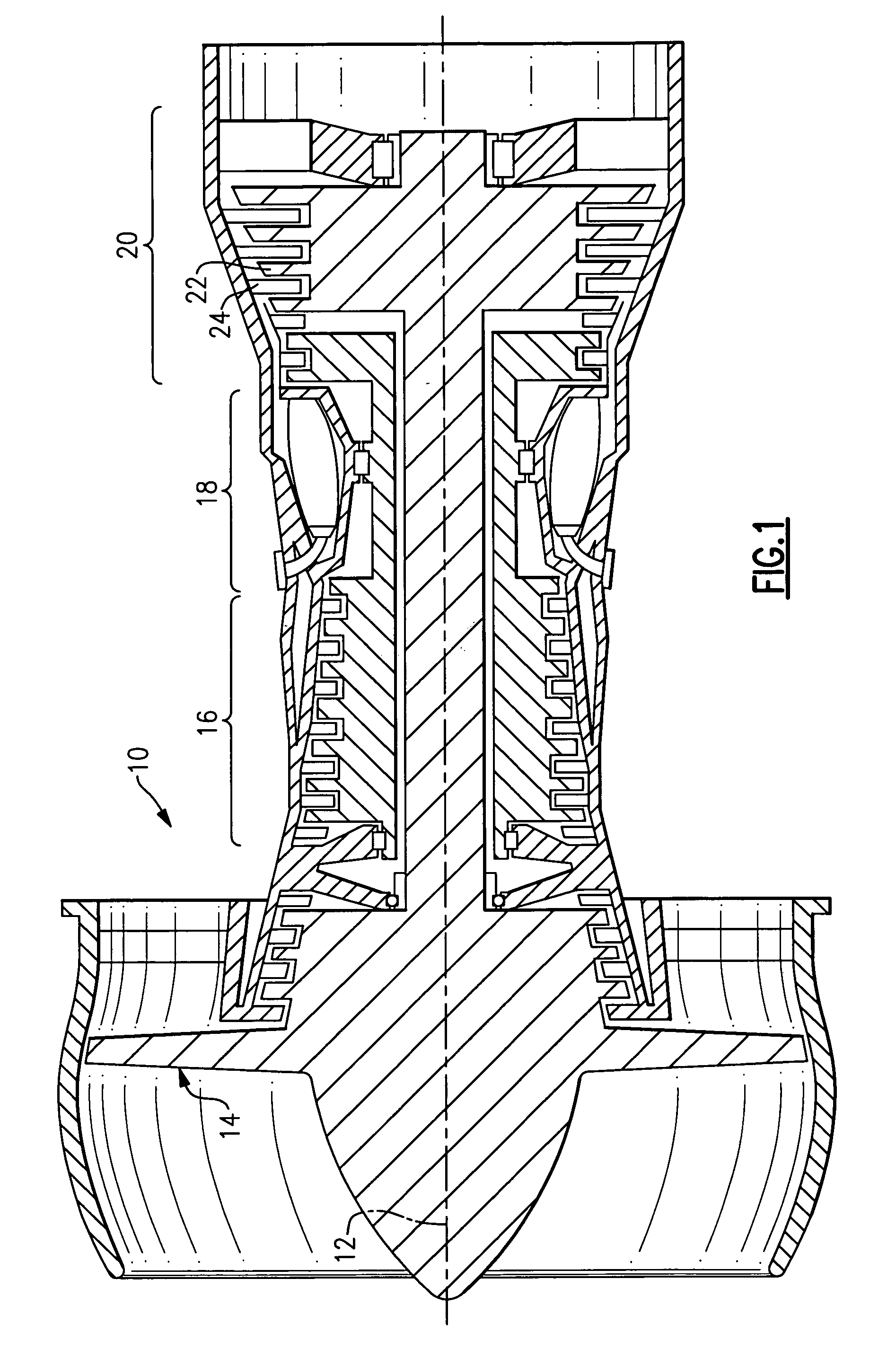
[0019]FIG. 1 shows a gas turbine engine 10, such as a gas turbine used for power generation or propulsion, circumferentially disposed about an engine centerline 12. The engine 10 includes a fan 14, a compressor section 16, a combustion section 18 and a turbine section 20 that includes a turbine blades 22 and turbine vanes 24. As is known, air compressed in the compressor section 16 is mixed with fuel that is burned in the combustion section 18 to produce hot gases that are expanded in the turbine section 20. FIG. 1 is a somewhat schematic presentation for illustrative purposes only and is not a limitation on the instant invention, which may be employed on gas turbines for electrical power generation, aircraft, etc. Additionally, there are various types of gas turbine engines, many of which could benefit from the present invention, which is not limited to the design shown.

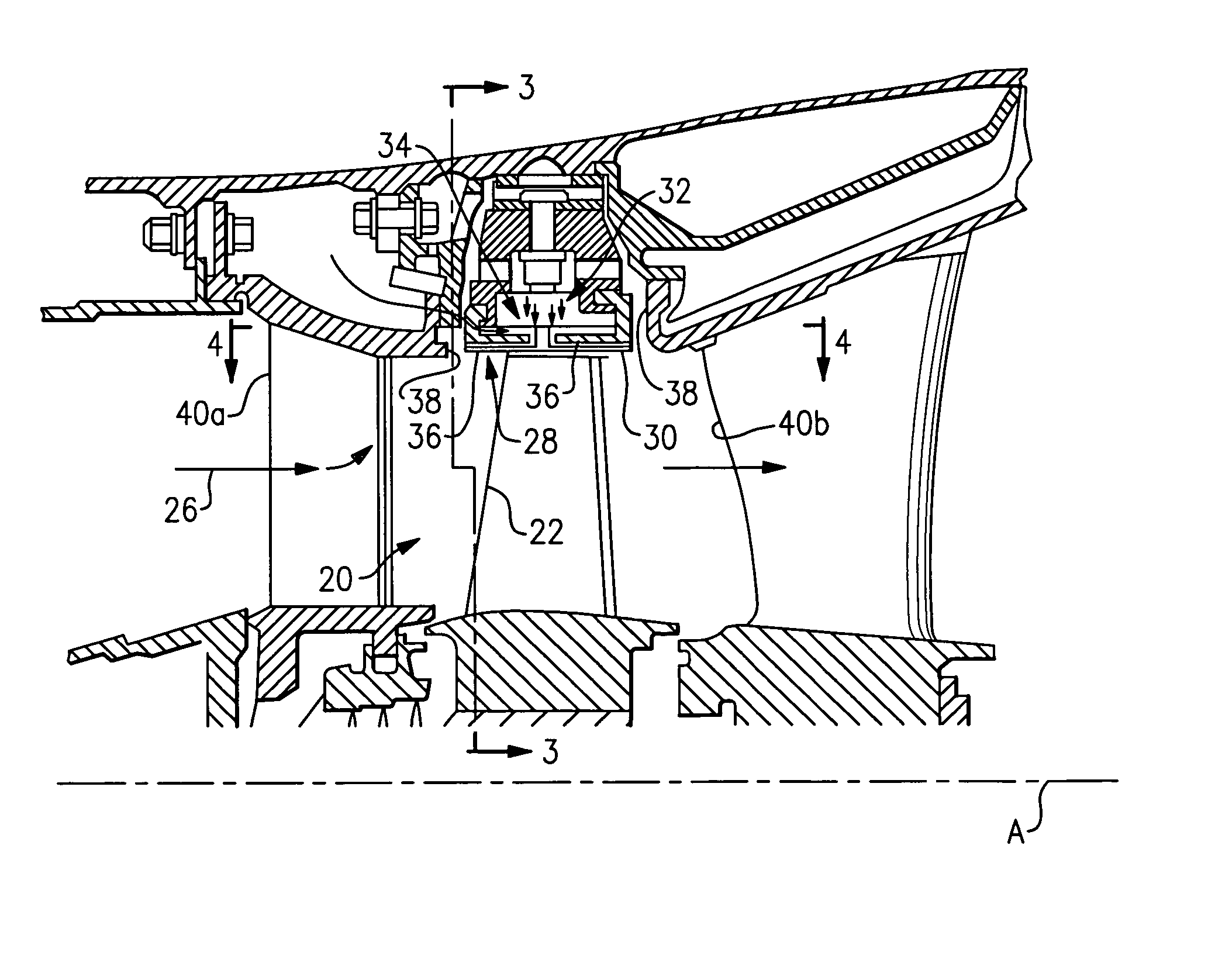
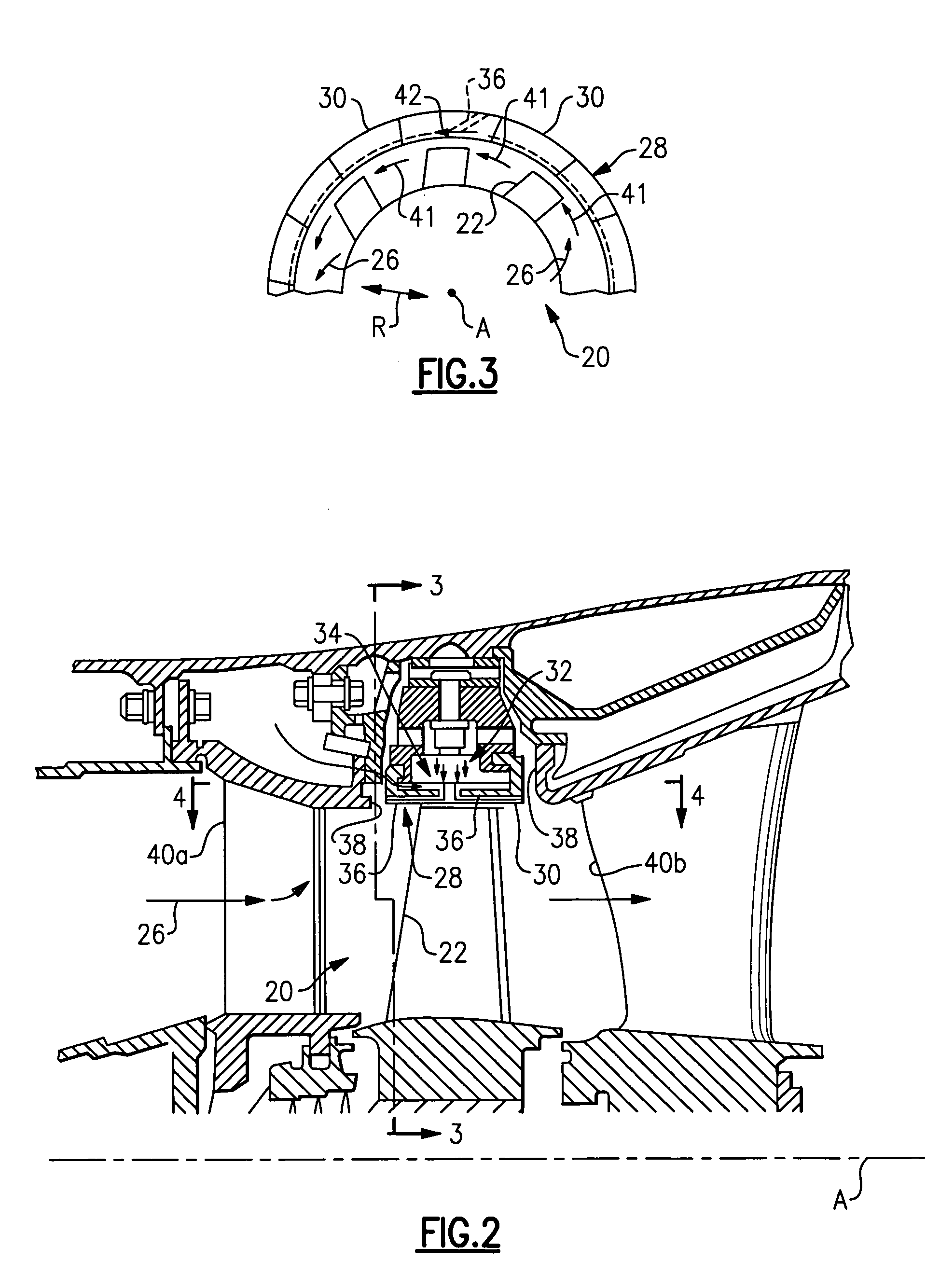
[0020]FIG. 2 illustrates a selected portion of the turbine section 20. The turbine blade 22 receives a hot gas fl...


PUM


Abstract

A turbine shroud section includes a cooling passage that bleeds cooling air through an opening in a surface. The cooling passage forms an angle relative to an expected fluid flow direction. The angle defines an angular component in a circumferential direction, which is aligned with the expected fluid flow direction to reduce momentum energy loss of fluid flow through the engine.

Description

[0001]This invention was made with government support under Contract No. F33615-03-D-2354-0001 awarded by the United States Air Force. The government therefore has certain rights in this invention.BACKGROUND OF THE INVENTION[0002]This invention relates to gas turbine engine shrouds and, more particularly, to a shroud having cooling passages that increase efficiency of the gas turbine engine.[0003]Conventional gas turbine engines are widely known and used to propel aircraft and other vehicles. Typically, gas turbine engines include a compressor section, a combustor section, and a turbine section. Compressed air from the compressor section is fed to the combustor section and mixed with fuel. The combustor ignites the fuel and air mixture to produce a flow of hot gases. The turbine section transforms the flow of hot gases into mechanical energy to drive the compressor. An exhaust nozzle directs the hot gases out of the gas turbine engine to provide thrust to the aircraft or other vehic...

Claims


Application Information

Patent Timeline
Patent Type & Authority Patents(United States)
IPC IPC(8): F03B11/00
CPCF01D11/24
Inventor LUTJEN, PAUL M.ROMANOV, DMITRIYDRAKE, JEREMYGROGG, GARYREINHARDT, GREGORY E.
Owner RTX CORP
Why Eureka
Try Eureka