
Power limiting circuit

a power limiting circuit and circuit technology, applied in the field of electrical circuits, can solve the problems of easy overheating, risk of battery explosion, damage to the electrical circuit or nearby components, etc., and achieve the effect of fabricated economics

Active Publication Date: 2008-02-26
NAT SEMICON CORP
View PDF12 Cites 14 Cited by
  • Summary
  • Abstract
  • Description
  • Claims
  • Application Information

AI Technical Summary

Benefits of technology

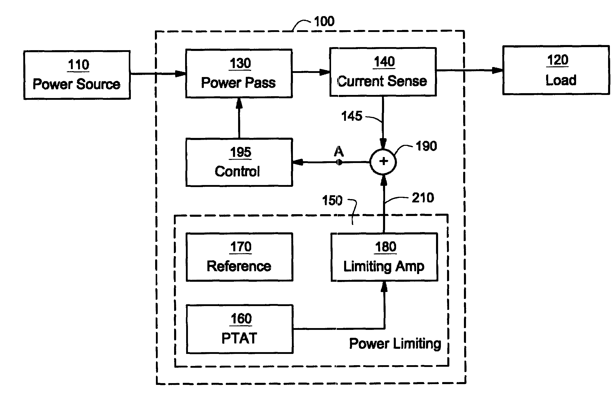
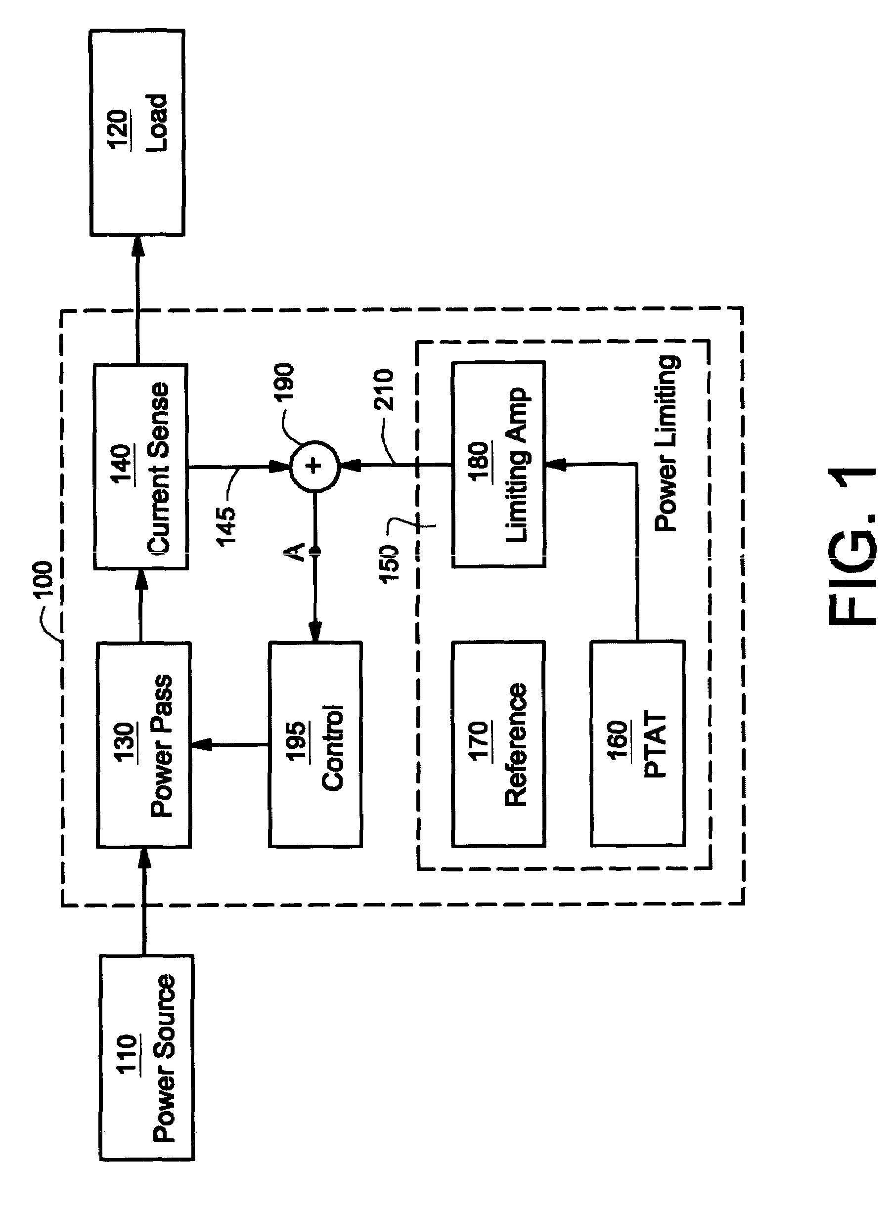
"The present invention provides a thermal protection circuit for electronic circuits that does not cause unnecessary stress to the power delivery systems they protect. The circuit uses a temperature sensing circuit and a regulation circuit that operates in a proportional manner to the temperature. The circuit also includes a power pass circuit that is controlled by a control signal based on the temperature signal and a feedback signal. The technical effects of the invention include improved thermal protection for electronic circuits and compatibility with existing semiconductor fabrication techniques."

Problems solved by technology

Without thermal protection, the electronic circuit or nearby components can be damaged, or at least rendered less efficient.
In the case of a battery charging circuit, overheating can damage the battery and even lead to risk of the battery exploding.
Without a thermal protection circuit, overheating can easily happen due to the charging current passing through elements having some resistance.
However, this complicates the circuit design and increases manufacturing expense.
Moreover, other circuit elements on the integrated circuit also dissipate heat.
Unfortunately, turning the circuit off and on causes “bounce”, which stresses the integrated circuit.

Method used


Image

  • Power limiting circuit
  • Power limiting circuit
  • Power limiting circuit

Examples


Embodiment Construction

[0015]Reference will now be made in detail to the preferred embodiments of the invention, examples of which are illustrated in the accompanying drawings. While the invention will be described in conjunction with the preferred embodiments, it will be understood that they are not intended to limit the invention to these embodiments. On the contrary, the invention is intended to cover alternatives, modifications and equivalents, which may be included within the spirit and scope of the invention as defined by the appended claims. Furthermore, in the following detailed description of the present invention, numerous specific details are set forth in order to provide a thorough understanding of the present invention. However, it will be obvious to one of ordinary skill in the art that the present invention may be practiced without these specific details. In other instances, well-known methods, procedures, components, and circuits have not been described in detail as not to unnecessarily ob...


PUM


Abstract

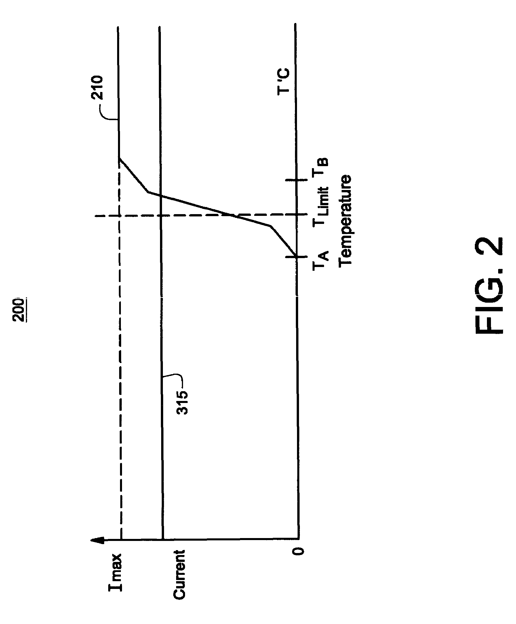
A power limiting circuit is disclosed. The power limiting circuit includes a temperature sensing circuit that outputs a temperature signal that is proportional to temperature over a temperature range. The power limiting circuit also includes a regulation circuit coupled to the temperature sensing circuit and controlled by the temperature signal. The regulation circuit operates in a manner that is proportional to the temperature.

Description

RELATED CASE[0001]This application is related to co-pending, commonly-owned U.S. patent application Ser. No. 10 / 652,991, filed Aug. 28, 2003, entitled “Method and System for Charge Current Control” to Potanin et al.TECHNICAL FIELD[0002]The present invention generally pertains to the field of electronic circuits. More particularly, embodiments of the present invention are related to a circuit for limiting power.BACKGROUND ART[0003]Many electronic circuits have a need for thermal protection. Without thermal protection, the electronic circuit or nearby components can be damaged, or at least rendered less efficient. Voltage regulators and battery chargers are two examples of circuits needing thermal protection, although many other circuits also need thermal protection. In the case of a battery charging circuit, overheating can damage the battery and even lead to risk of the battery exploding. Without a thermal protection circuit, overheating can easily happen due to the charging current...

Claims


Application Information

Patent Timeline
Patent Type & Authority Patents(United States)
IPC IPC(8): H02H5/04
CPCH02H5/041H02H9/026
Inventor POTANIN, VLADISLAVPOTANINA, ELENA
Owner NAT SEMICON CORP
Learn More