
Image processing apparatus, image reading apparatus, image forming apparatus and recording medium for image processing program

a technology of image processing and reading apparatus, which is applied in the direction of visual presentation, geometric image transformation, instruments, etc., can solve the problems of synthesis process that requires a large processing time, image output apparatus and image display apparatus, laser printers and inkjet printers, and remarkable quality increases

Inactive Publication Date: 2008-02-26
RICOH KK
View PDF20 Cites 22 Cited by
  • Summary
  • Abstract
  • Description
  • Claims
  • Application Information

AI Technical Summary

Benefits of technology

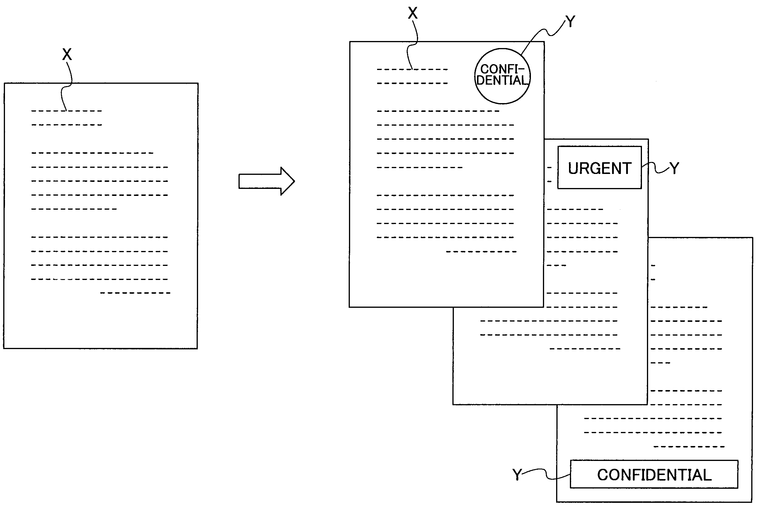
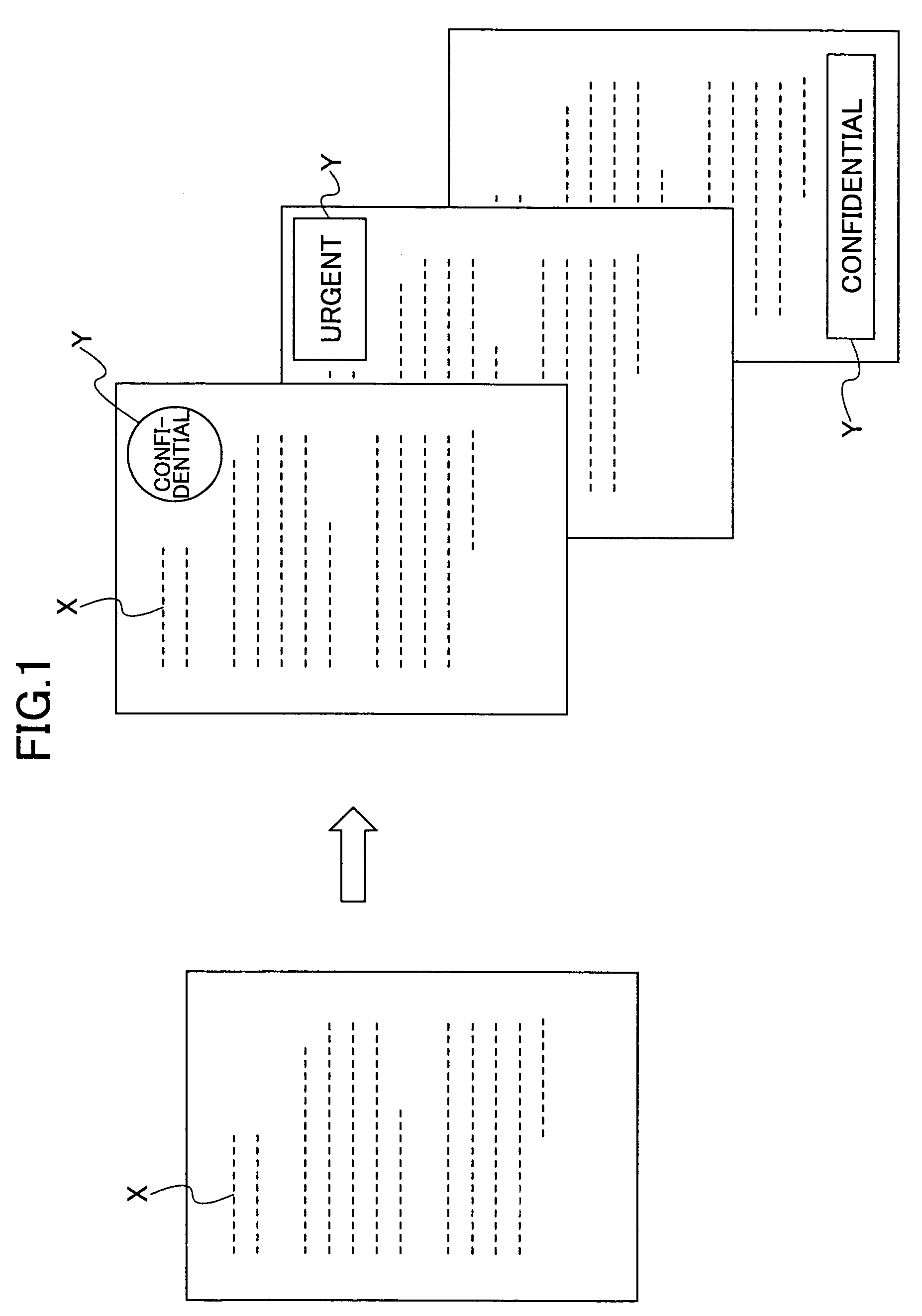
The present invention provides an image processing apparatus that can efficiently synthesize coded data from a source image and a target image using the JPEG 2000 standard with less use of memory and higher speed. The apparatus uses a search part to identify coded data of an objective block that matches the designated synthesis area in the source image. The objective block synthesis part synthesizes coded data of the objective block by replacing the coded data of the source image with the coded data of the target image. The apparatus can also use a tile with header information for a more efficient synthesis process. Overall, the invention provides an improved image processing apparatus for synthesizing images.

Problems solved by technology

On the other hand, image output apparatuses and image display apparatuses, such as laser printers and inkjet printers, are also experiencing remarkable quality increases and drastic price decreases.
However, such a synthesis process requires a large processing time, because the resulting encoded image is obtained through the decoding process, the image synthesis process, and the encoding process.

Method used


Image

  • Image processing apparatus, image reading apparatus, image forming apparatus and recording medium for image processing program
  • Image processing apparatus, image reading apparatus, image forming apparatus and recording medium for image processing program
  • Image processing apparatus, image reading apparatus, image forming apparatus and recording medium for image processing program

Examples


first embodiment

[0120]A description is given, with reference to FIG. 19 and FIG. 20, of an image synthesis process according to the present invention.

[0121]The above-mentioned digital color copier 1 has an image synthesis mode as one of image editing functions thereof. The digital color copier 1 according to the present invention makes the most use of advantages of the JPEG 2000 standard, so that the digital color copier 1 can synthesize images by performing a decoding process on the corresponding coded data fewer execution times. In an image synthesis process according to the first embodiment, images are synthesized per tile including header information. In this case, the digital color copier 1 can perform the synthesis process on a tile independently of other tiles.

[0122]The digital color copier 1 may read a source image and a target image, which are to be synthesized, from underlying documents and then may temporarily store these images in MEM 48. However, the digital color copier 1 according to...

second embodiment

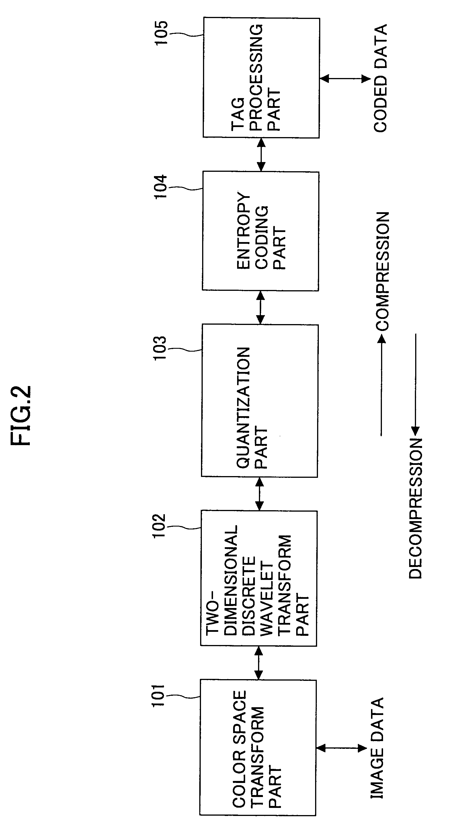
[0146]FIG. 21 is a portion of a flowchart of the synthesis process according to the Referring to FIG. 21, if an objective tiles corresponding to one of identified synthesis positions is detected (S9: YES), the data decompression part 68 partially decodes coded data of the objective tile of the source and target images, that is, the decompression part 68 performs only an inverse wavelet transform on the coded data to reconstruct not image data but wavelet coefficients. Then, the system controller 44 stores the reconstructed wavelet coefficients in RAM 44b at step S21. Step S21 is implemented by an objective wavelet coefficient reconstruction part and an objective wavelet coefficient reconstruction function.

[0147]At step S22, the system controller 44 synthesizes the wavelet coefficients of the source and target images in RAM 44b. Step S22 is implemented by an objective wavelet coefficient synthesis part and an objective wavelet coefficient synthesis function.

[0148]At step S23, the da...

third embodiment

[0159]FIG. 23 is a portion of a flowchart of a synthesis process according to the Referring to FIG. 23, if an objective tile corresponding to one of the identified synthesis positions is detected (S9: YES), the system controller 44 simply replaces original coded data of the objective tile of the source image in MEM 48 with coded data of the objective tile of the target image at step S31. Step S31 is implemented by both a coded data replacement part and an objective block synthesis part or both a coded data replacement function and an objective block synthesis function. After the replacement, the resulting coded data are stored in MEM 48. The above-mentioned process is repeated for all objective tiles.

[0160]FIGS. 24A through 24C are diagrams illustrating an example for explaining the above-mentioned synthesis process. FIG. 24A shows coded data of an exemplary source image as in FIGS. 20A and 22A. Referring to FIG. 24A, the source coded data are partitioned into tiles TA01 through TA...


PUM


Abstract

An image processing apparatus, an image reading apparatus, an image forming apparatus and a computer-readable recording-medium for storing an image processing program are disclosed. The image processing apparatus can synthesize coded data encoded in accordance with JPEG 2000 standard from source and target images at a higher speed with less use of a memory. The image processing apparatus includes a search part and an objective block synthesis part. The search part searches coded data of the source image per predetermined independently processable block for an objective block corresponding to a designated synthesis area. The objective block synthesis part synthesizes detected coded data of the objective block of the source image and coded data of the objective block of the target image.

Description

BACKGROUND OF THE INVENTION[0001]1. Field of the Invention[0002]The present invention generally relates to an image processing apparatus, an image reading apparatus, an image forming apparatus and a recording medium for storing an image processing program.[0003]2. Description of the Related Art[0004]Recent developments of techniques associated with input and output of images have strongly stimulated a demand for higher-definition images. For example, digital still cameras, which are a kind of image input apparatuses, are in widespread use at present because of rapid price reduction of high-performance charge coupled devices (CCD), which play an integral part in the digital still cameras, that have the number of effective pixels greater than three millions. On the other hand, image output apparatuses and image display apparatuses, such as laser printers and inkjet printers, are also experiencing remarkable quality increases and drastic price decreases. In addition, such phenomena can...

Claims


Application Information

Patent Timeline
Patent Type & Authority Patents(United States)
IPC IPC(8): G06K9/36G06T3/00H04N1/387H04N1/41
CPCH04N1/41
Inventor NOMIZU, YASUYUKISAKUYAMA, HIROYUKIHARA, JUNICHIMATSUURA, NEKKAYANO, TAKANORIKODAMA, TAKUMIYAZAWA, TOSHIOSHINKAI, YASUYUKINISHIMURA, TAKAYUKI
Owner RICOH KK
Learn More