Parallel kinematics mechanism with a concentric spherical joint
Inactive Publication Date: 2008-03-04
ROY SHAMBHU NATH +1
View PDF15 Cites 3 Cited by
Summary
Abstract
Description
Claims
Application Information
AI Technical Summary
This helps you quickly interpret patents by identifying the three key elements:
Problems solved by technology
Method used
Benefits of technology
[0028]Another advantage of the invention is that, in an embodiment, it provides a mechanism which has a modular and non-redundant design that only uses five actuator limbs, four of which are identical, two kinds of joint assemblies, a base, an actuator, and a work tool. The low number of parts and the usage of mostly revolute joints or simple ball-and-socket joints results in a precise and cost-efficient positioning mechanism that finds wide use in many areas.
[0029]In a further embodiment, a parallel kinematics mechanism according to the present invention has five actuated elbow-linkages with actuator arms and forearms, the elbow-linkages being arranged to rotate about a common central axis. The mechanism further includes a linkage that influences the position of a first elbow-linkage depending on the state of one or more of the other elbow-linkages. Advantageously, the actuator arms of a second and third elbow-linkage operate in the same plane perpendicular to the central axis while the first elbow-linkage operates in a plane parallel to the central axis. The first elbow-linkage is rotated by the actuator arms of the second and third elbow-linkage and constrained to following their movements in order to achieve symmetric workspace conditions and a favorable structural stiffness of the mechanism. Preferably, the first elbow-linkage remains midway between the second and third elbow-linkage.
[0030]A further object of the invention is to provide a mechanism to position an end component in space with at least three translational degrees of freedom and fixed orientation. The mechanism includes only three actuated elbow-linkages, a first of which comprises of an actuated first limb member and a second limb member, a second and third of which comprise of an actuator arm and two forearms. A first joint assembly links the second limb member of the first elbow-linkage with one forearm of the second and third elbow linkage, while a second joint assembly interconnects the remaining forearm of the second and third elbow-linkage. The two joint assemblies tog
Problems solved by technology
The design of the proposed mechanism reduces calculations to the simple problem of finding the point of intersection of three spher
Method used
Image
Click on the blue label to locate the original text in one second.
Reading with bidirectional positioning of images and text.
Examples
Example
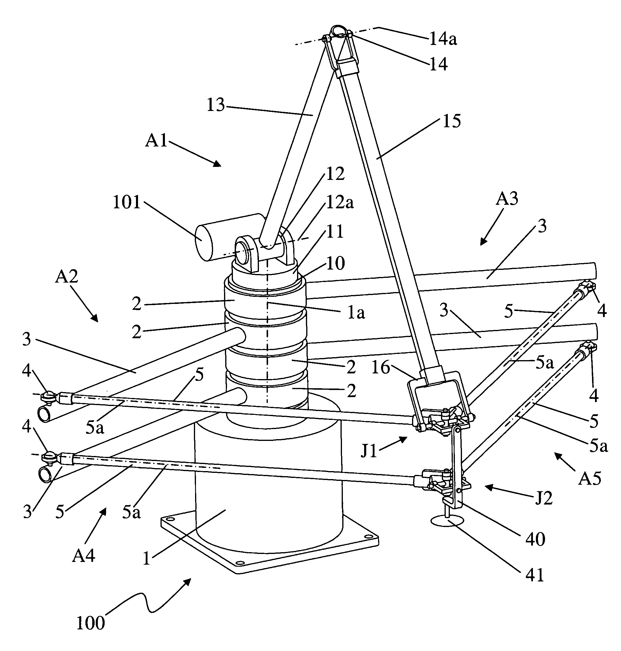
[0055]Now referring to the drawings, wherein like numerals designate like components, FIG. 1 shows a five-axis parallel kinematics mechanism 100 constructed in accordance with teachings of the present invention. Mechanism 100 includes a fixed base 1 and is operable to position and orient an end component 40 in space relative to the base 1 with five degrees of freedom. The position and orientation of the end component 40 are determined by five actuator limbs A1, A2, A3, A4, and A5, as will be described.
[0056]As illustrated in FIG. 1, mechanism 100 includes a first tetrahedral structure formed by first, second, and third actuator limbs A1, A2, A3. Actuator limb A1 is an actuated elbow-linkage device comprising of a platform 11, a first limb member 13, and a second limb member 15. The platform 11 is movably mounted to the base 1 by a revolute joint 10, allowing free rotation of platform 11 relative to the base 1 about a central axis 1a. Moreover, an actuated revolute joint 12 connects ...
PUM
Abstract
A parallel kinematics mechanism is provided for uses such as robotics or machining. The mechanism has various limbs designed as elbow-linkages, at least some of which are actuatable, for moving an end component with multiple degrees of freedom. The mechanism advantageously facilitates an improved workspace-to-footprint ratio and a closed-form solution for the forward kinematics. The mechanism comprises a joint assembly having a plurality of revolute joints for connecting to at least three limbs. In various embodiments of the invention, the end component has three, four, five and six degrees of freedom.
Description
[0001]This patent application is a continuation-in-part of U.S. patent application Ser. No. 10 / 619,134, filed Jul. 15, 2003 now abandoned, which is a continuation-in-part of U.S. patent application Ser. No. 10 / 278,701, filed Oct. 23, 2002, now U.S. Pat. No. 6,648,583, granted Nov. 18, 2002, which is a divisional of U.S. patent application Ser. No. 09 / 368,856, filed Aug. 5, 1999, now U.S. Pat. No. 6,497,548, granted Dec. 24, 2002.BACKGROUND[0002]The present invention generally relates to an apparatus with multiple limbs for positioning and orienting an end component in space and to joints for linking limbs of such an apparatus.[0003]A need exists for simple and effective parallel kinematics mechanisms. Kinematics mechanisms are used in mechanical engineering applications for machining, robotics, positioning devices, coordinate measuring, fixtures and so on. In general, mechanisms can be classified as either serial or parallel. Serial kinematics mechanisms are widely used and presentl...
Claims
Application Information
Patent Timeline
Application Date:The date an application was filed.
Publication Date:The date a patent or application was officially published.
First Publication Date:The earliest publication date of a patent with the same application number.
Issue Date:Publication date of the patent grant document.
PCT Entry Date:The Entry date of PCT National Phase.
Estimated Expiry Date:The statutory expiry date of a patent right according to the Patent Law, and it is the longest term of protection that the patent right can achieve without the termination of the patent right due to other reasons(Term extension factor has been taken into account ).
Invalid Date:Actual expiry date is based on effective date or publication date of legal transaction data of invalid patent.