Traffic cone counterweight structure

a technology of counterweight structure and traffic cone, which is applied in the direction of roads, roads, construction, etc., can solve the problems of high production cost of traffic cone, material waste, and considerable technical challenges, and achieve the effects of improving the existing traffic cone structure, saving material cost, and enhancing the utilization value and economic benefi

Inactive Publication Date: 2008-03-04
JING NAN TRAFFIC ENG
View PDF11 Cites 20 Cited by
  • Summary
  • Abstract
  • Description
  • Claims
  • Application Information

AI Technical Summary

Benefits of technology

[0008]In view of the problems and drawbacks present in the prior art, this inventor embarked on research with the aim to improve the existing traffic cone structure, and based on many years of experience and know-how in the industry, developed a traffic cone counterweight structure disclosed in the present invention. The primary object of the present invention is to allow the base and the cone body of a traffic cone to be fabricated in separate processes and allow the use of low-price material for making the base of traffic cone without compromising the warning effect and weight requirement of traffic cones, thereby achieving savings in material cost and greatly enhancing its utilization value and economic benefit.
[0009]Another object of the present invention is to allow the use of an existing mold for making an integrally-formed traffic cone, where the base is preformed and then placed in the mold for the making of cone body by injection molding. Manufacturers only need to fabricate different base molds to meet different counterweight requirements, and use the existing movable die blocks of mold for making integrally-formed traffic cone to assemble traffic cones of different counterweights. As such, the mold costs are reduced significantly, and there is no time-consuming and tedious operation of mold change in order to produce traffic cones with different counterweights, thereby greatly enhancing the production efficiency and offering excellent economic benefit.
[0010]Yet another object of the present invention is that through structural design, it allows the use of material with less fluidity or recycled material for the making of the base of the traffic cone, or even the use of scrap material, such as waste tire, to make the base of traffic cone by stamping and extruding, thereby achieving the dual economic benefits of waste recycling and reuse, and cost reduction.
[0011]To achieve the aforesaid objects, the structural design of the present invention calls for fabricating the traffic cone in separate processes, in which, the base is first preformed, and then assembled to the cone body by injection molding, so that material possessing less fluidity or recycled material, or even scrap material, such as waste tire, can be used to fabricate the base by injection molding or stamping and extruding. As such, the material cost for the base is reduced without adversely affecting the warning effect and weight requirement of the traffic cone. Moreover, the existing mold for making integrally-formed traffic cone is used directly for the fabrication of traffic cone without the need to make additional molds, thereby offering excellent utilization value and economic benefit.

Problems solved by technology

As a result, the production cost of traffic cones stay high.
On the other hand, if cost is a prime consideration and material with poor fluidity is used for injection molding, the cone body tends to break or results in defects during molding, which leads instead to material waste.
In addition, traffic cones have a counterweight requirement, which poses a considerable technical challenge in the production process.
Generally materials with better fluidity cost more.
As such, the aforementioned patents effectively address the counterweight issue of traffic cone, but tend to jack up its production cost, thus lacking utilization value and economic benefit, and leaving room for improvement.
Under the circumstances, traffic cone manufacturers must make separate molds for the cone body and base with different counterweight specifications, which greatly increases the mold cost.
In fact, the increase in cost far surpasses the saving achieved by using low-priced material, hence lacking economic benefit.
Moreover, when making traffic cones with different counterweight specification, the mold needs to be changed and calibrated, which is time consuming, thereby adversely affecting the production efficiency.
Thus the design for traffic cones mentioned above is hardly ideal.

Method used


Image

  • Traffic cone counterweight structure
  • Traffic cone counterweight structure
  • Traffic cone counterweight structure

Examples


Embodiment Construction

[0018]The structural composition, technical means and effects of the invention are described in detail below with embodiments in reference to the accompanying drawings.

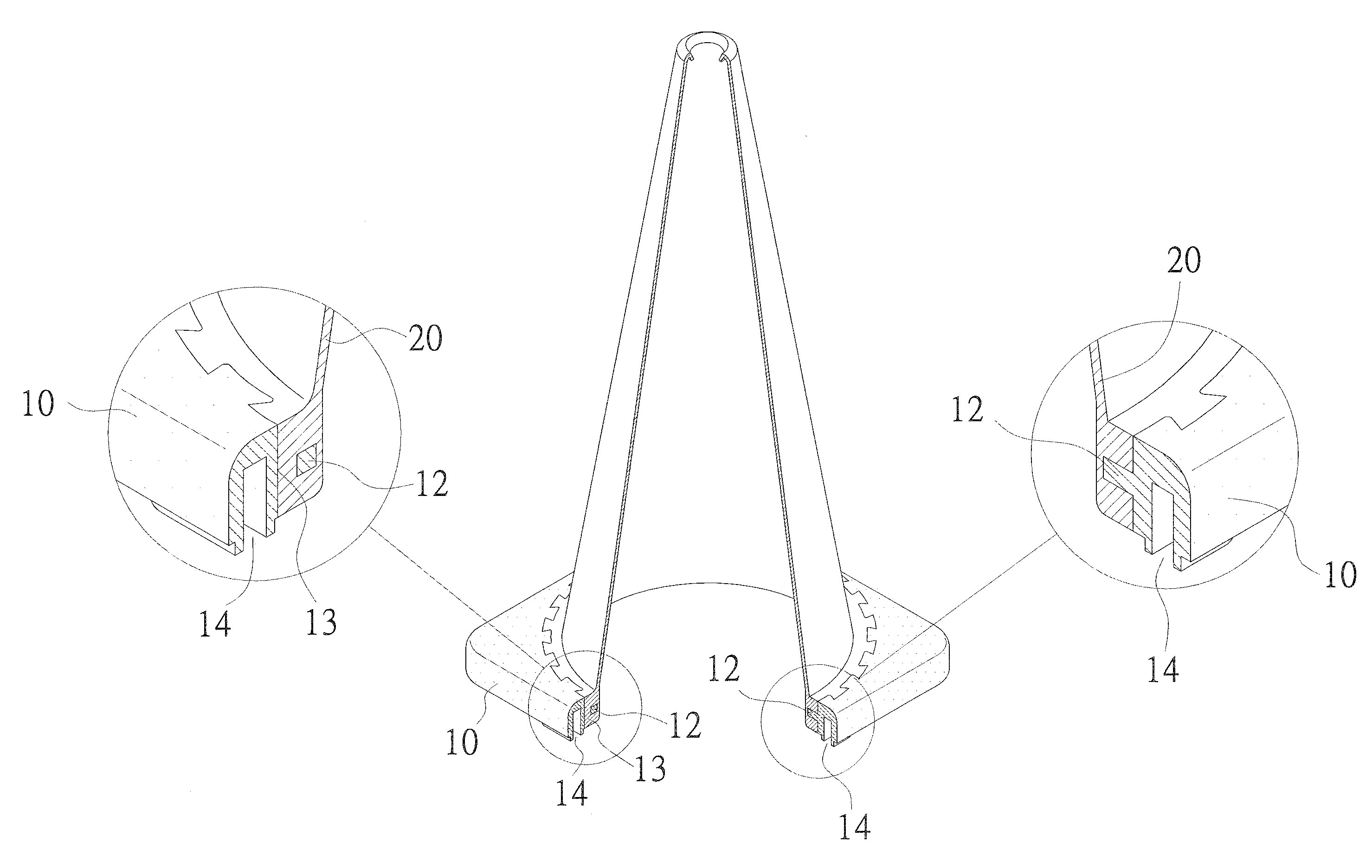
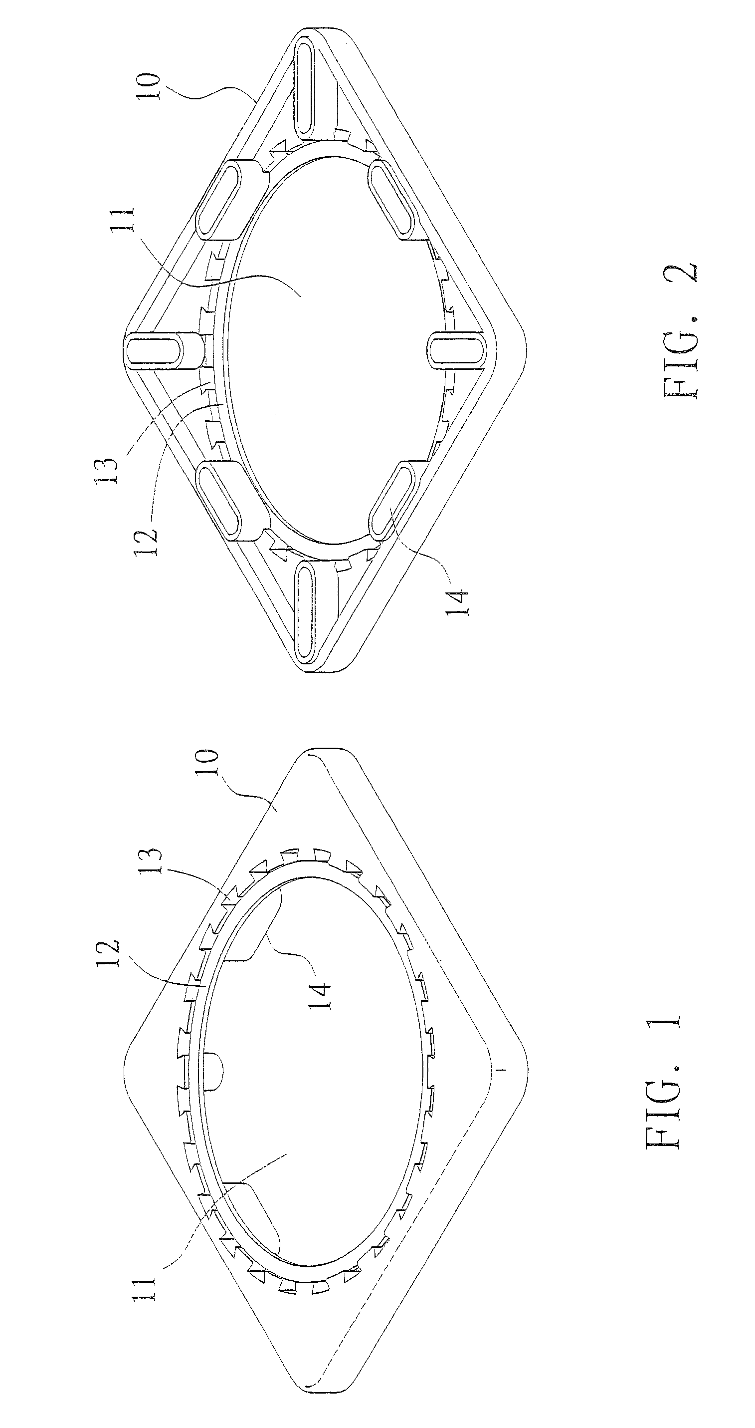
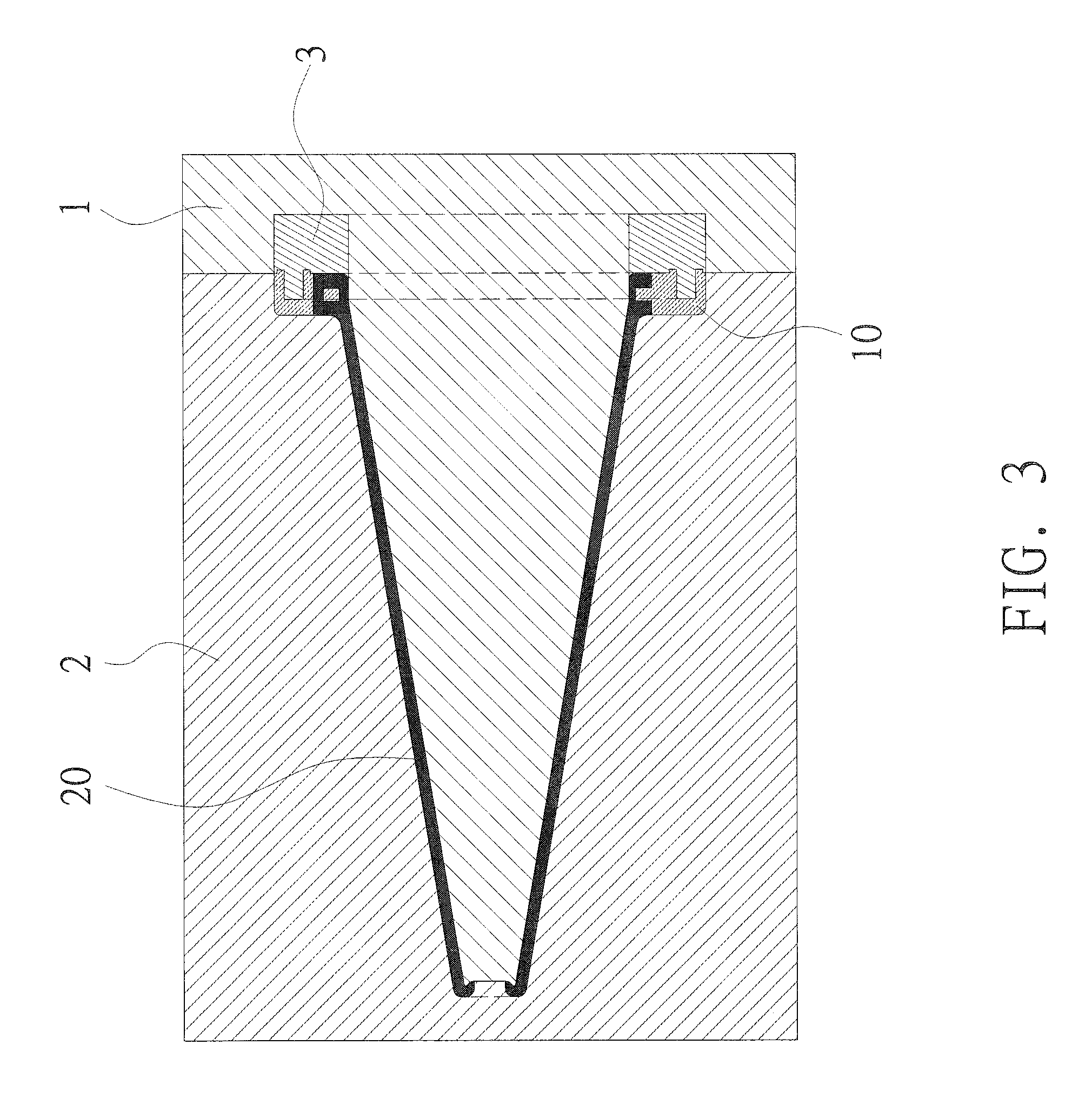
[0019]Referring to the structural diagrams in FIGS. 1, 2 and 5, the assembly structural relations diagrams in FIGS. 3 and 4, and the structural relations diagram in FIG. 6, the structural design for a preferred embodiment of the invention calls for fabricating the base 10 and the cone body 20 of a traffic cone in separate processes, wherein the base 10 is preformed, and then placed in a traffic cone mold for the injection molding of cone body 20.

[0020]Based on actual needs, separately fabricated base molds can be used to make bases with various counterweight configurations. There is provided a large-diameter opening 11 at the center of the base 10 for coupling the cone body 20 in an injection molding process. The mid-section along the inner edge of the opening 11 is extendedly disposed with a convex ring member 12 of ...


PUM


Abstract

A traffic cone counterweight structure, the base of the cone is preformed with a large-diameter opening at the center having a convex ring member of proper width at its mid-section along the inner edge. A plurality of dovetail through holes are annularly configured along the circumference of the opening of base at where it adjoins the convex ring member. The preformed base is placed in an existing mold for making an integrally-formed traffic cone for injection molding of cone body. The better fluidity material that is used for the cone body flows through the preformed dovetail through holes on the base to wrap around the convex ring member to conjoin the base and the cone body.

Description

BACKGROUND OF THE INVENTION[0001]1. Field of the Invention[0002]The present invention relates to a traffic cone counterweight structure designed primarily for saving the production cost of traffic cones. The traffic cone is made by first fabricating its base and then forming the cone body by injection molding. As such, the base of traffic cone can be made of materials with less fluidity or recycled material, or even scrap material from waste tires by stamping and extruding, thereby reducing the material cost of the base without compromising the original warning effect of the traffic cone and its counterweight requirement. Also, the production of such traffic cones can use existing molds for making integrally-formed traffic cones directly without the need to fabricate a separate mold, hence offering excellent utilization value and economic benefit for the industry.[0003]2. Description of the Related Art[0004]Conventional traffic cones are made of plastic or rubber material in one pie...

Claims


Application Information

Patent Timeline
Patent Type & Authority Patents(United States)
IPC IPC(8): E01F9/012E01F9/00
CPCE01F9/0122E01F9/688E01F9/654
Inventor KUO, SHU-NAN
Owner JING NAN TRAFFIC ENG
Why Eureka
Try Eureka