Non-constant pressure infusion pump

a non-constant pressure, infusion pump technology, applied in the direction of instruments, process and machine control, other medical devices, etc., can solve the problems of fluid flow rate such devices are susceptible to changes in ambient temperature and pressure, the propellant-reservoir pressure of conventional gas-driven infusion pumps is relatively large, and the use of battery power is relatively larg

Inactive Publication Date: 2008-03-04
ADVANCED NEUROMODULATION SYST INC
View PDF14 Cites 143 Cited by
  • Summary
  • Abstract
  • Description
  • Claims
  • Application Information

AI Technical Summary

Benefits of technology

[0021]Another objective of the present invention is to provide an implantable infusion device that is simpler in construction.

Problems solved by technology

These devices have certain advantages; however, such devices have a large disadvantage in that they use relatively large amounts of battery power to effect infusion.
The propellant-reservoir pressure of conventional gas-driven infusion pumps are susceptible to changes in ambient temperature and pressure.
This, in turn, makes the fluid flow rate such devices susceptible to changes in ambient temperature and pressure.
Such changes in drug infusion rates are undesirable and, in certain situations, unacceptable.
In addition, changes in environmental temperature affect the infusate viscosity as well as the vapor pressure produced by the propellant, thereby further increasing the pump's susceptibility to temperature.
An even more serious situation results from changes in ambient pressure.
These infusion devices possess undesirable attributes in that refilling operations are more difficult and the high-pressure vessels, which form the pump housing structures, must necessarily be stronger and are therefore more susceptible to manufacturing problems.
In addition to increasing the operational complexity of such a pump mechanism and the volume of a fluid path extending therethrough, the pressure regulator may, depending upon device configuration, subject infusate solutions to high local shear stresses, which may alter the chemical or therapeutic properties of certain infusates.
While this configuration offers practical performance advantages, this design offers a unique configuration that may not be adopted by all constant flow pump designs.

Method used


Image

  • Non-constant pressure infusion pump
  • Non-constant pressure infusion pump
  • Non-constant pressure infusion pump

Examples


Embodiment Construction

[0042]Various embodiments, including preferred embodiments, will now be described in detail below with reference to the drawings.

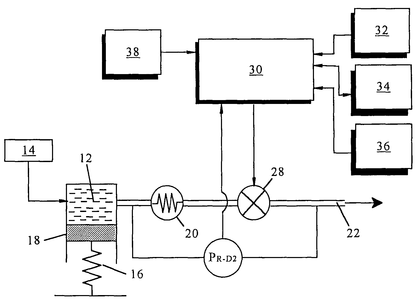
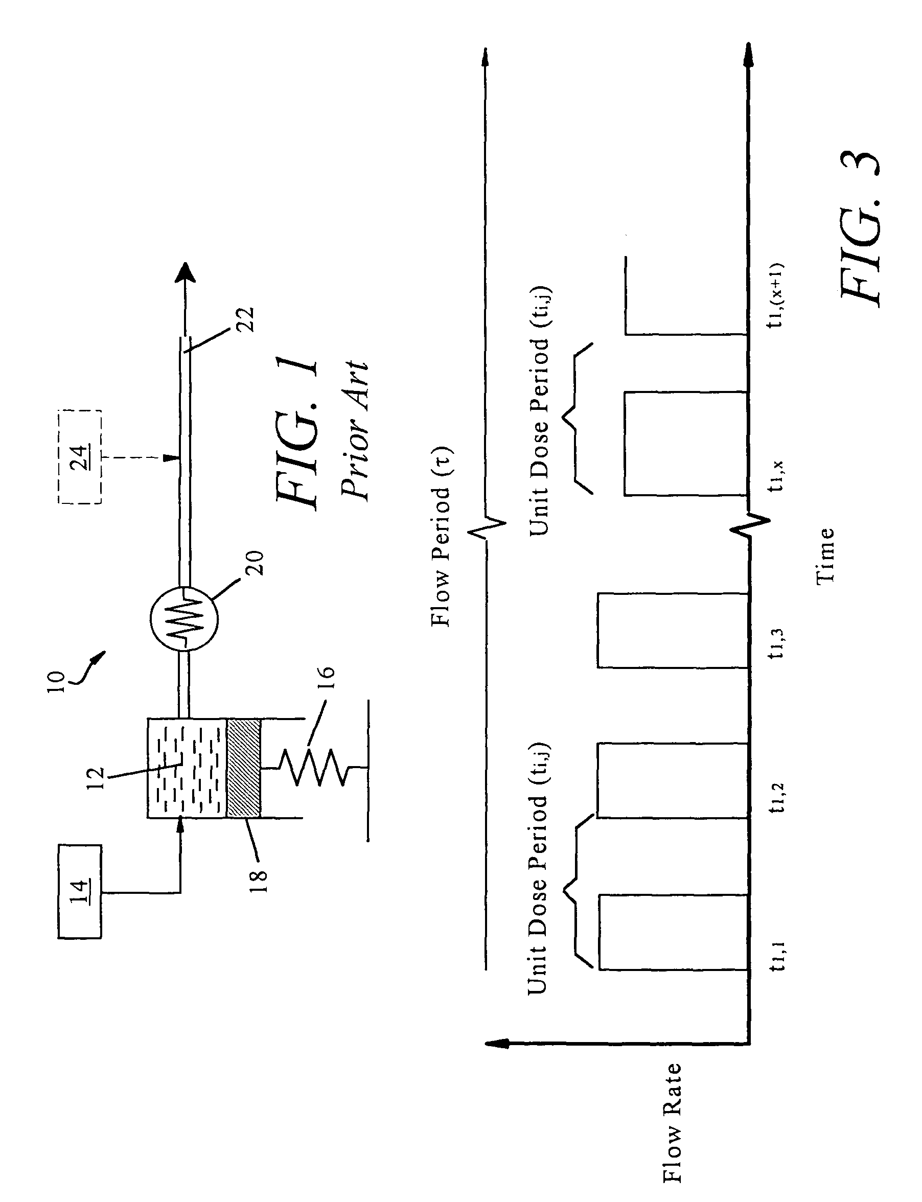
[0043]FIG. 1 illustrates a conventional, constant flow rate infusion device 10. The device 10 is characterized by an infusate reservoir 12 that is required to store a prescribed volume of infusate, e.g., insulin, medicament, pain relieving drugs, etc. The infusate reservoir 12 is of sufficient volume so as to provide a supply of infusate (i.e., a prescribed dose (D)) over a flow period (τ) at a (theoretically) constant flow rate. As but one possible example, the volume of the infusate reservoir 12 can be fixed at any prescribed volume to enable delivery of a precisely controlled volume of infusate from one day to more than three months. The infusate reservoir 12 can be refilled through a septum 14.

[0044]Infusate is pressurized and thereby driven from the infusate reservoir 12 by a drive source 16. The physical nature of the drive source 16 can be a two-pha...


PUM


Abstract

The present invention relates to an implantable infusion pump having a refillable infusate reservoir in fluid communication with a delivery site via a flow path. This flow path includes a flow resistance. The infusion pump includes a sensing device(s), positioned relative to the flow path, to provide data regarding a flow rate along the flow path. The infusion pump effects a division of a total flow period into at least a plurality of unit dose periods, each unit dose period effecting delivery of a unit dose of infusate. The cumulative effect of delivering the total number of unit dose periods is the delivery of a desired dose over the total flow period. The present invention permits a reservoir pressure to vary over any portion of total flow period but effects a constant-pressure state over each unit dose cycle.

Description

CROSS-REFERENCE TO RELATED APPLICATIONS[0001]The present invention is a continuation of, and hereby claims priority to, copending and commonly assigned U.S. patent application Ser. No. 09 / 796,969 entitled “Non-Constant Pressure Infusion Pump,” filed Mar. 1, 2001, now U.S. Pat. No. 6,620,151, the disclosure of which is hereby incorporated herein by reference.FIELD OF THE INVENTION[0002]The present invention relates to an implantable infusion pump, and in particular, to an infusion pump capable of effecting a precisely controlled (constant or variable) fluid flow delivery rate, independent of a constant reservoir pressure.BACKGROUND OF THE INVENTION[0003]Modern implantable infusion devices, or implantable pumps, for delivering an infusate (e.g., medicaments, insulin, etc.) commonly have a rigid housing that maintains a collapsible infusate reservoir. The housing includes a needle-penetrable septum that covers a reservoir inlet. A flow passage is provided between the reservoir and an e...

Claims


Application Information

Patent Timeline
Patent Type & Authority Patents(United States)
IPC IPC(8): A61M31/00A61K9/22A61M5/142A61M5/145A61M5/168
CPCA61M5/14276A61M5/1452A61M5/16881A61M2005/14264A61M2005/14506A61M2205/33A61M2205/3372
Inventor BLISCHAK, BRIANERICKSON, JOHN H.DAGLOW, TERRYHOOPER, SANDRA M.WIGNESS, BRUCE D.
Owner ADVANCED NEUROMODULATION SYST INC
Why Eureka
Try Eureka