Methods and apparatus for preventing the migration of intradiscal devices

a technology of intradiscal devices and preventing migration, which is applied in the field of artificial intervertebral disc replacement and repair, can solve the problems of reduced disc degeneration treatment

Inactive Publication Date: 2008-03-04
FERREE BRET A
View PDF16 Cites 149 Cited by
  • Summary
  • Abstract
  • Description
  • Claims
  • Application Information

AI Technical Summary

Benefits of technology

[0014]Broadly according to this invention, barriers are used to hold intradiscal devices in position while allowing movement of the vertebrae and the intradiscal device independent of one another. In the preferred embodiments, the barrier is in the form of a “buttress” plate coupled to a controlled linka

Problems solved by technology

The nucleus becomes thinner and less able to handle compression loads.
The redundant annular fibers are less effective in controlling vertebral motion.
Current surgical treatments of disc degeneration are destructive.
These destructive procedures lead to acceleration of disc degeneration.
The first two groups of procedures compromise the tre

Method used


Image

  • Methods and apparatus for preventing the migration of intradiscal devices
  • Methods and apparatus for preventing the migration of intradiscal devices
  • Methods and apparatus for preventing the migration of intradiscal devices

Examples


Embodiment Construction

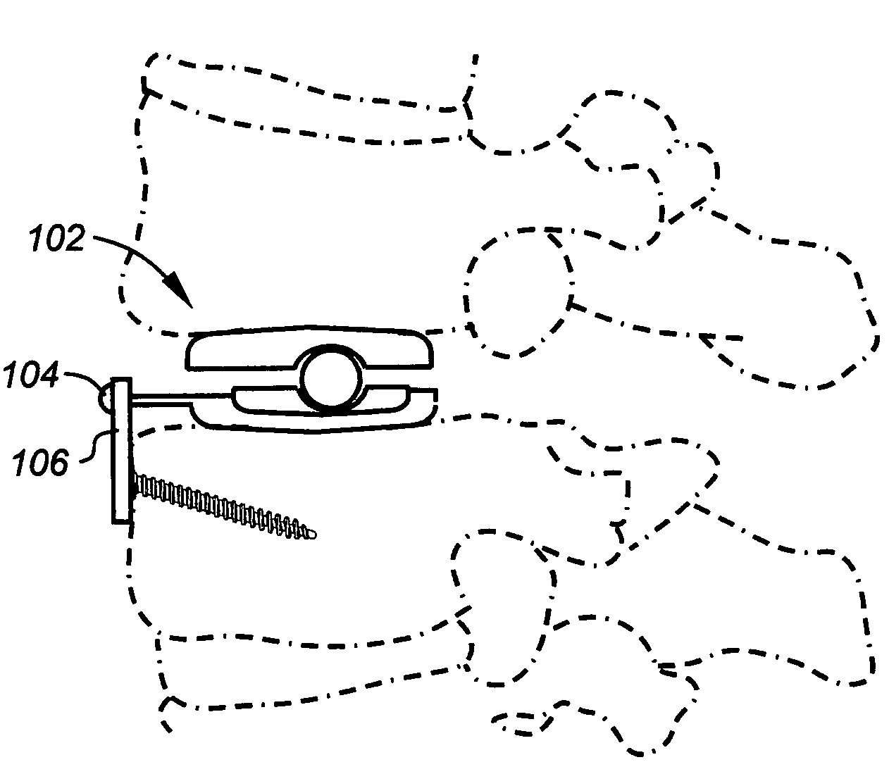
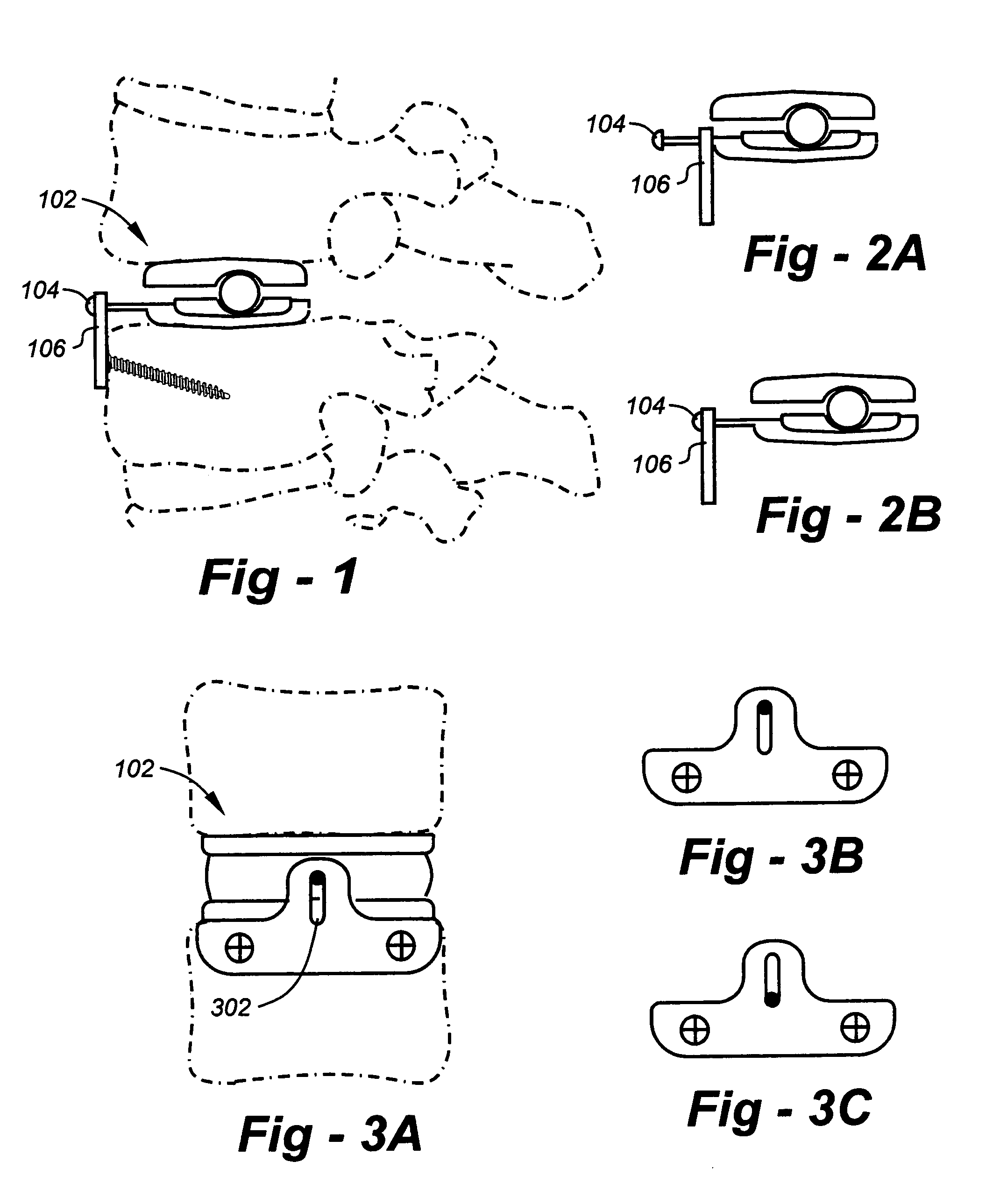
[0040]Reference is now made to the drawings, wherein FIG. 1 shows an ADR 102 with an extension 104 to link the ADR to the barrier plate 106, the link member 104 may attach to both the ADR and the barrier plate. Attachment of the link member through a swivel joint to the ADR would further increase the degrees of freedom of motion. The plate and / or link member may be made of metal, polymer, or other suitable material. In addition, the screw holes in the barrier plate may contain an anti-back out feature and converge or diverge.

[0041]FIG. 2A is a side-view drawing of an artificial disc replacement (ADR) coupled to a barrier plate through a link member assuming a first position, and FIG. 2B is a drawing of the configuration of FIG. 2A showing how the link member allows the ADR to piston back and forth through a controlled range of motion.

[0042]FIG. 3A is a front-view drawing of a barrier plate 302 having a slot which permits vertical movement and angulation. FIG. 3B shows one extent of ...


PUM


Abstract

Barriers are used to hold prosthetic components, including intradiscal devices, in position while allowing natural movement within a “safe zone.” In the preferred embodiments, the barrier is in the form of a “buttress” plate coupled to a controlled linkage that prevents the device from moving into a dangerous position. The movable member(s) allow an intradiscal device to move through a safe zone while permitting mobile artificial disc replacements (ADRs) or other intradiscal devices to self-center with movement of the vertebrae. The link member(s) broadly serve as a “tether” to prevent extrusion of the intradiscal device into the spinal canal, or outside of the disc space. The intradiscal device may be mobile, or attached to one or both of the vertebral endplates. Other mechanisms to accommodate the movable link members are also disclosed. The plates are preferably constructed of metal, but the invention is not limited in terms of the biocompatible material(s) used for the plate or link members.

Description

REFERENCE TO RELATED APPLICATION[0001]This application claims priority from U.S. Provisional Patent Application Ser. No. 60 / 376,505, filed Apr. 30, 2002, the entire content of which is incorporated herein by reference.FIELD OF THE INVENTION[0002]This invention relates generally to artificial intervertebral disc replacement and repair and, in particular, to apparatus for maintaining intradiscal devices in position, while allowing movement of the vertebrae and the intradiscal device independent of one anotherBACKGROUND OF THE INVENTION[0003]Seven cervical (neck), 12 thoracic, and 5 lumbar (low back) vertebrae form the normal human spine. Intervertebral discs reside between adjacent vertebra with two exceptions. First, the articulation between the first two cervical vertebrae does not contain a disc. Second, a disc lies between the last lumbar vertebra and the sacrum (a portion of the pelvis).[0004]The spine supports the body, and protects the spinal cord and nerves. The vertebrae of t...

Claims


Application Information

Patent Timeline
IPC IPC(8): A61F2/44A61F2/30A61B17/70A61B17/86A61F2/00
CPCA61F2/442A61B17/7059A61B17/86A61F2002/30369A61F2002/30462A61F2002/30517A61F2002/30578A61F2002/443A61F2220/0025A61F2220/0033A61F2220/0075Y10S606/914
Inventor FERREE, BRET A.
Owner FERREE BRET A
Why Eureka
Try Eureka