
Magnetic shielding apparatus and biomagnetism measuring device

a technology of magnetic shielding apparatus and measuring device, which is applied in the direction of magnetic field measurement using superconductive devices, instruments, applications, etc., can solve the problems of deteriorating the magnetic shielding factor of the cylindrical magnetic shielding apparatus, limited space where the apparatus can be installed, and high cost, so as to achieve excellent workability and operability, and high sensitivity. , the effect of excellent feeling

Active Publication Date: 2008-03-04
HITACHI HIGH-TECH CORP
View PDF5 Cites 8 Cited by
  • Summary
  • Abstract
  • Description
  • Claims
  • Application Information

AI Technical Summary

Benefits of technology

The invention is a small-sized magnetic shielding apparatus for measuring biomagnetism. The apparatus has a large magnetic shielding factor and is designed to minimize the impact of environmental magnetic fields on the measurements. The apparatus is easy to install and has a simple structure. However, existing methods for inserting an object of examination into the apparatus have limitations, such as the need for a large room and the difficulty of adjusting the position of the object of examination. The invention provides a solution by providing an improved method for inserting the object of examination and a more comfortable interior situation for the examination engineer. The apparatus is also designed to minimize the impact on the examination object and to enhance the operability of the examination engineer.

Problems solved by technology

As generally, the longitudinal, the lateral and the height dimensions of a floor of the conventional type magnetic shielding apparatus which is the box-type chamber are approximately 2 m and the conventional type magnetic shielding apparatus is heavy, the conventional type has a problem that a room where the apparatus can be installed is limited and in addition, the cost is also high.
However, as the opening is close to the SQUID fluxmeter and a direction in which an environmental (external) magnetic field invades is parallel to a direction of a magnetic field measured by the SQUID fluxmeter, there is a problem that the existence of the opening deteriorates the magnetic shielding factor of the cylindrical magnetic shielding apparatus.
In the above-mentioned method (1) of inserting an object of examination inside the cylindrical magnetic shielding apparatus, as no door is provided, the method has a merit that the structure is simple, however, the method has a problem that it is difficult for an examination engineer to observe an inside situation of the magnetic shielding apparatus and it is difficult for him / her to precisely adjust a position of examination.
Besides, as a bed is required to be pulled out in a direction of the cylindrical axis to mount the object of examination on the bed, the method has a problem that a room is required to have the length of approximately 4 m so as to install the magnetic shielding apparatus if the length in the direction of the cylindrical axis of the magnetic shielding apparatus is approximately 2 m.

Method used


Image

  • Magnetic shielding apparatus and biomagnetism measuring device
  • Magnetic shielding apparatus and biomagnetism measuring device
  • Magnetic shielding apparatus and biomagnetism measuring device

Examples


first embodiment

[0352]FIGS. 29 to 59 show a cardiac magnetic field measuring device equivalent to a first embodiment. FIG. 29 is an outside drawing showing the device, FIG. 30 is a block diagram showing the device, FIG. 31 shows a principle of measurement, FIGS. 32 to 48 are structural drawings showing the details of each device, FIGS. 49 to 54 show used states, FIGS. 55 to 58 are explanatory drawings for explaining a positioning device for positioning a subject, and FIGS. 62A to 62C show another combination.

[0353]First, referring to FIGS. 29 and 30, the schematic structure of the cardiac magnetic field measuring device equivalent to this embodiment will be described. FIG. 29 is an outside drawing showing the cardiac magnetic field measuring device. FIG. 30 is a block diagram showing the cardiac magnetic field measuring device.

[0354]As shown in FIGS. 29 and 30, the cardiac magnetic field measuring device includes a gantry 200 for holding a measuring part 100 provided with a fluxmeter (hereinafter c...

second embodiment

[0511]Next, referring to FIGS. 60 to 62, the inside of a magnetic shield 300 will be described. FIGS. 60A to 60E are explanatory drawings showing the inside of the magnetic shield, FIG. 60A is a schematic sectional view, and FIGS. 60B to 60E show patterns on inner walls. FIGS. 61A and 61B are explanatory drawings showing a state in which an opening / closing body 304 is open, FIG. 61A is a schematic sectional view, and FIG. 61B shows a pattern on an inner wall viewed from the outside. FIGS. 62A to 62C are explanatory drawings showing a state in which the opening / closing body 304 is closed, FIGS. 62A and 62B are schematic sectional views, and FIG. 62C shows a pattern on the inner wall viewed inside shielded space.

[0512]First, referring to FIGS. 60A to 60E, rough structure in this embodiment will be described. In this embodiment, basic structure shown in FIGS. 60A to 60E is the similar structure to that in the first embodiment. This embodiment is greatly characterized in that a cardiac ...

third embodiment

[0521]Next, referring to FIGS. 63 to 65, a cardiac magnetic field measuring device equivalent to a third embodiment will be described. FIGS. 63A and 63B are perspective views showing the appearance of the cardiac magnetic field measuring device equivalent to the embodiment, FIG. 63A is the perspective view showing a state in which the opening / closing body 304 is open and FIG. 62B is the perspective view showing the opening / closing of the opening / closing body 304. FIGS. 64A to 64F are outside drawings showing the cardiac magnetic field measuring device, FIG. 64A is a plan, FIG. 64B is a bottom view, FIG. 64C is a front view, FIG. 64D is a right side view, FIG. 64E is a back view, and FIG. 64F is a left side view. FIG. 65 is a schematic sectional view showing the cardiac magnetic field measuring device.

[0522]This embodiment is first characterized in that a cylindrical holding body 350 is provided on one side of a cylindrical magnetic shield 300 to be overhung type structure and opposi...


PUM


Abstract

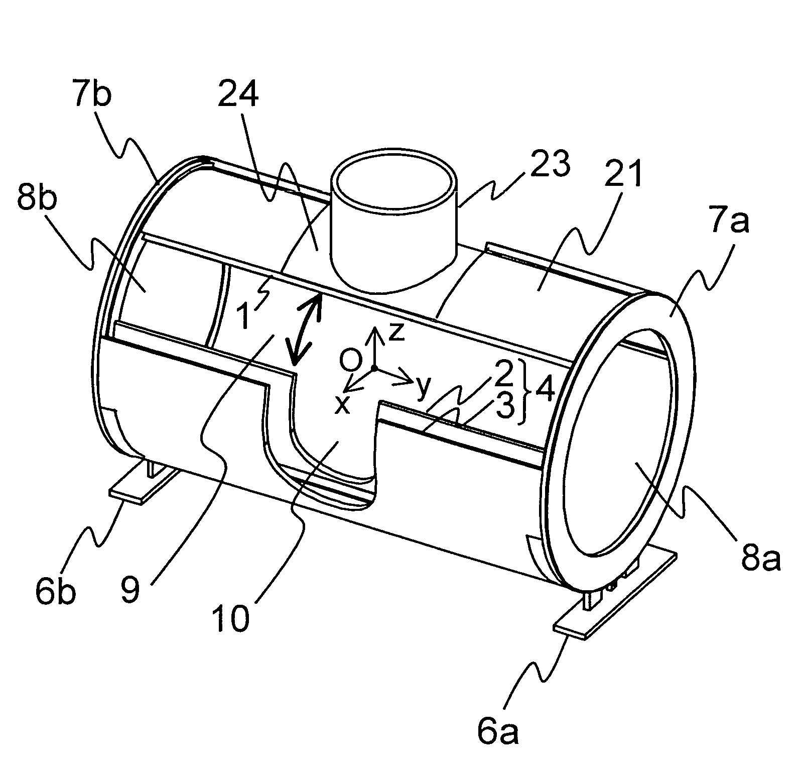
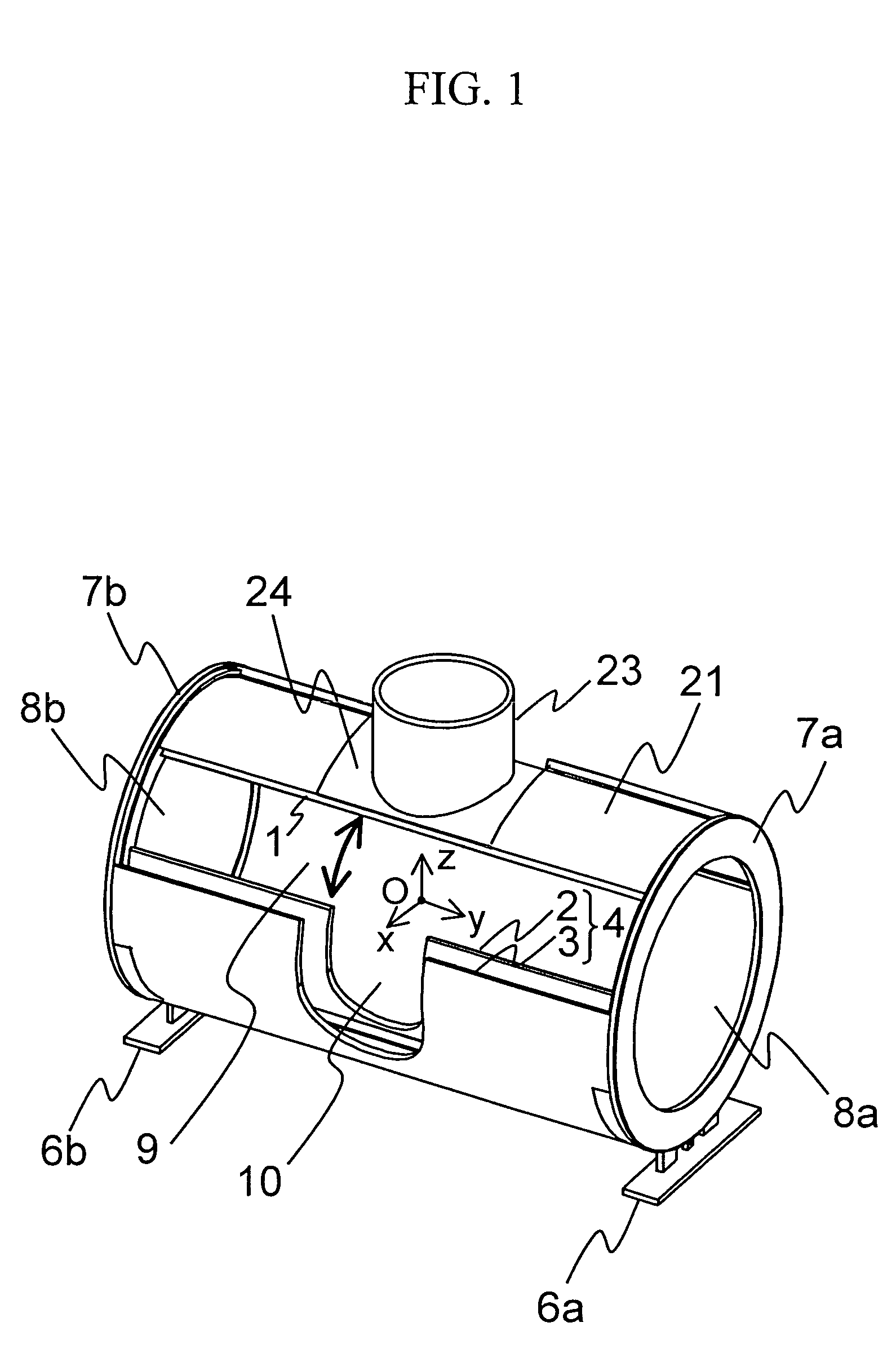
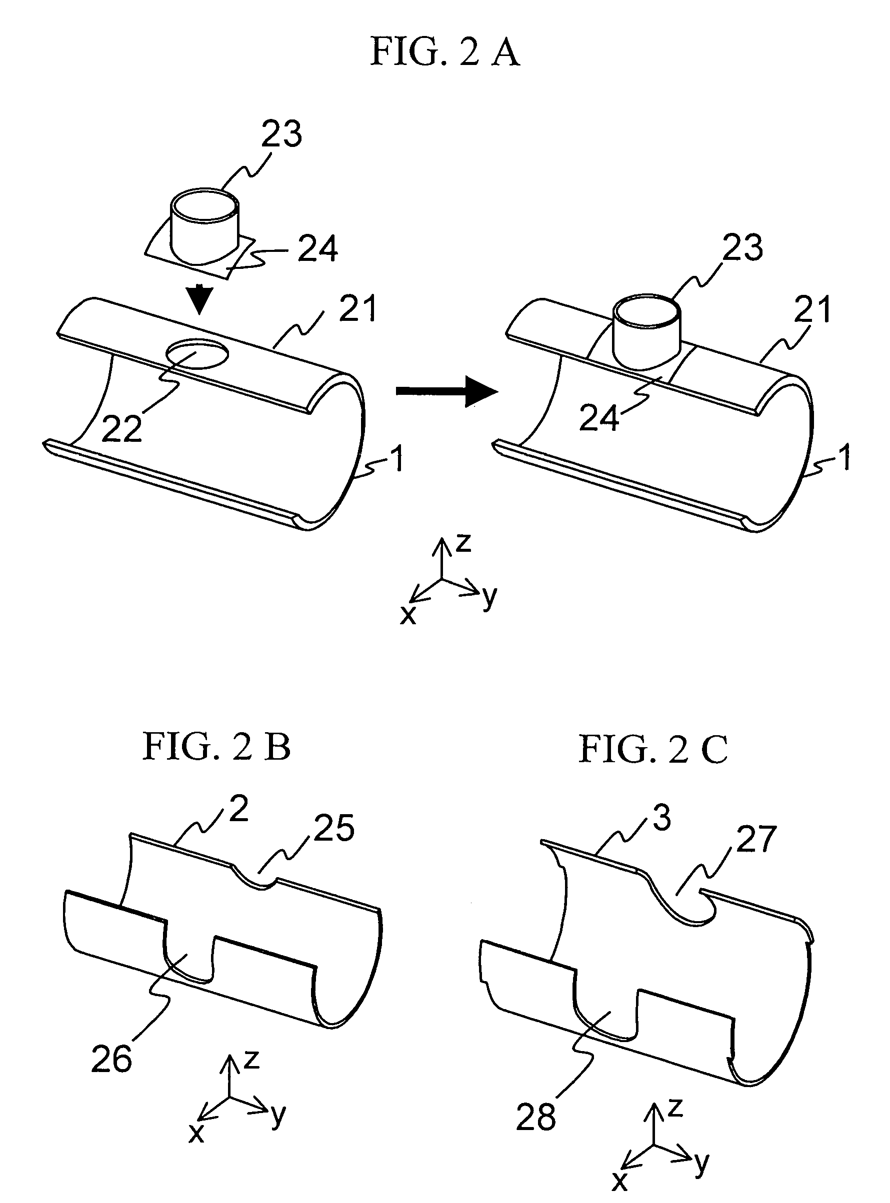
The object of the invention is to provide a biomagnetism measuring device using a high-performance cylindrical shielding apparatus provided with a flange-type plate having an opening formed on a circumferential face, an auxiliary cylinder in which one or plural cylindrical members are connected so that the central axis of the opening of the flange-type plate and each central axis of the cylindrical members are coincident, cylindrical shields having first, second and third angular ranges with the y-axis, a revolving door having a cutout in a portion parallel to the y-axis and acquired by integrating the cylindrical shields, shield bases for supporting the cylindrical shield to which the flange-type plate is connected in a circular-arc part at both ends, revolving parts for revolving the revolving door in a circumferential direction of the y-axis along a circumferential part of the cylindrical shield and opening or closing an opening in the circumferential direction, a cryostat arranged inside the opening of the auxiliary cylinder and the opening and a SQUID fluxmeter arranged on a measurement face parallel to an XY plane inside the cryostat held at low temperature and characterized in that the circumferential part of the cylindrical shield is inserted between the circumferential parts of the cylindrical shields when the revolving door is closed, cylindrical internal space is formed and an environmental magnetic field that invades the internal space is screened.

Description

CLAIM OF PRIORITY[0001]The present application claims priority from Japanese application JP No. 2004-263192 filed on Sep. 10, 2004, the contents of which are hereby incorporated by reference into this application.FIELD OF THE INVENTION[0002]The present invention relates to a magnetic shielding apparatus for shielding environmental magnetic noise, a biomagnetism measuring device using it, and a biomagnetism measuring method.BACKGROUND OF THE INVENTION[0003]Heretofore, a magnetic shielding apparatus which was used for measuring biomagnetism generated from an organism and which screened an environmental magnetic field (an external magnetic field) was manufactured by fastening and fixing a plate having high permeability (high-permeability material such as Permalloy) onto a frame made of aluminum and stainless steel without clearance by a bolt and others as a spatially closed box-type chamber. Besides, plates made of Permalloy were laminated, a magnetic shielding factor was enhanced, and...

Claims


Application Information

Patent Timeline
Patent Type & Authority Patents(United States)
IPC IPC(8): G01R33/035
CPCA61B5/04007A61B5/061A61B5/704Y10S505/846A61B5/243
Inventor SEKI, YUSUKEONUMA, MITSURUKANDORI, AKIHIKOSUZUKI, DAISUKEAKASHI, TAKUYAMURAKAMI, MASAHIROWATANABE, ATSUSHIMATSUOKA, YOSHIO
Owner HITACHI HIGH-TECH CORP
Learn More