Dynamic queue allocation and de-allocation

a dynamic and queue technology, applied in data switching networks, time-division multiplexing selection, multiplex communication, etc., can solve the problems of manual and time-consuming processes, inefficient use of network resources,

Inactive Publication Date: 2008-03-04
ALCATEL LUCENT SAS
View PDF14 Cites 24 Cited by
  • Summary
  • Abstract
  • Description
  • Claims
  • Application Information

AI Technical Summary

Benefits of technology

[0012]It should be appreciated, therefore, that the dynamic queue allocation of a preferred embodiment avoids the need for pre-configuring and pre-allocating queues in a static manner. The dynamic queue allocation further allows the...

Problems solved by technology

A drawback with the existing manner of configuring queues is that the process is manual and time consuming.
A further drawback with the existing configuration proce...

Method used


Image

  • Dynamic queue allocation and de-allocation
  • Dynamic queue allocation and de-allocation
  • Dynamic queue allocation and de-allocation

Examples


Embodiment Construction

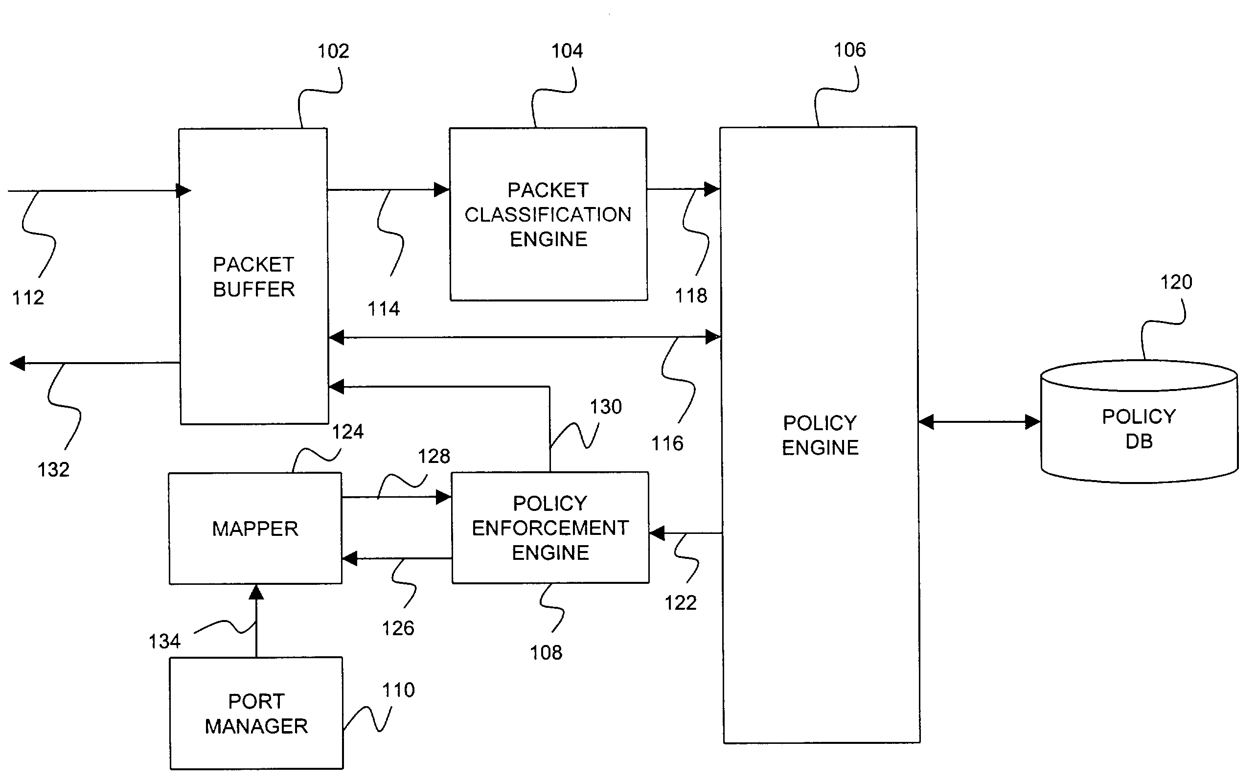
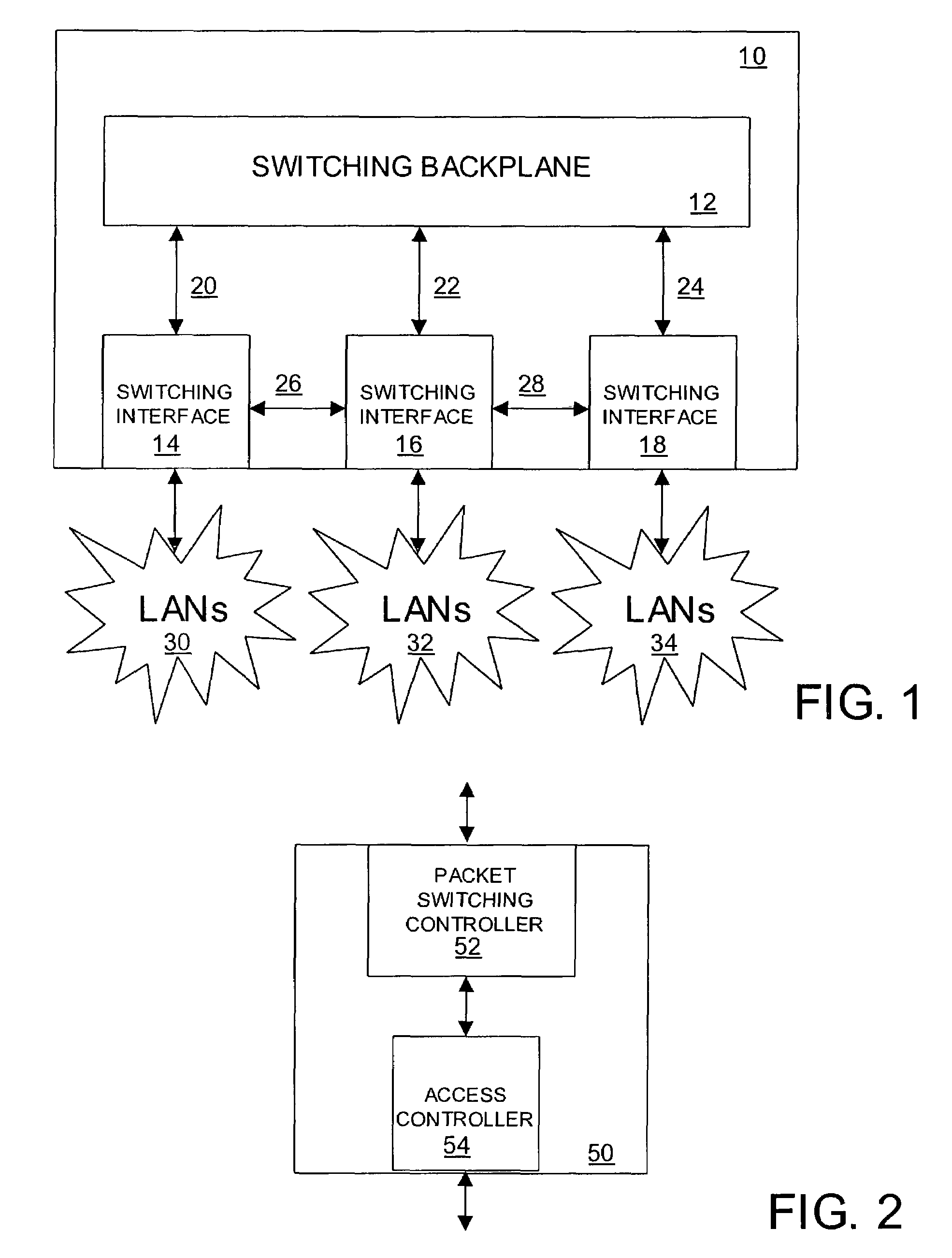
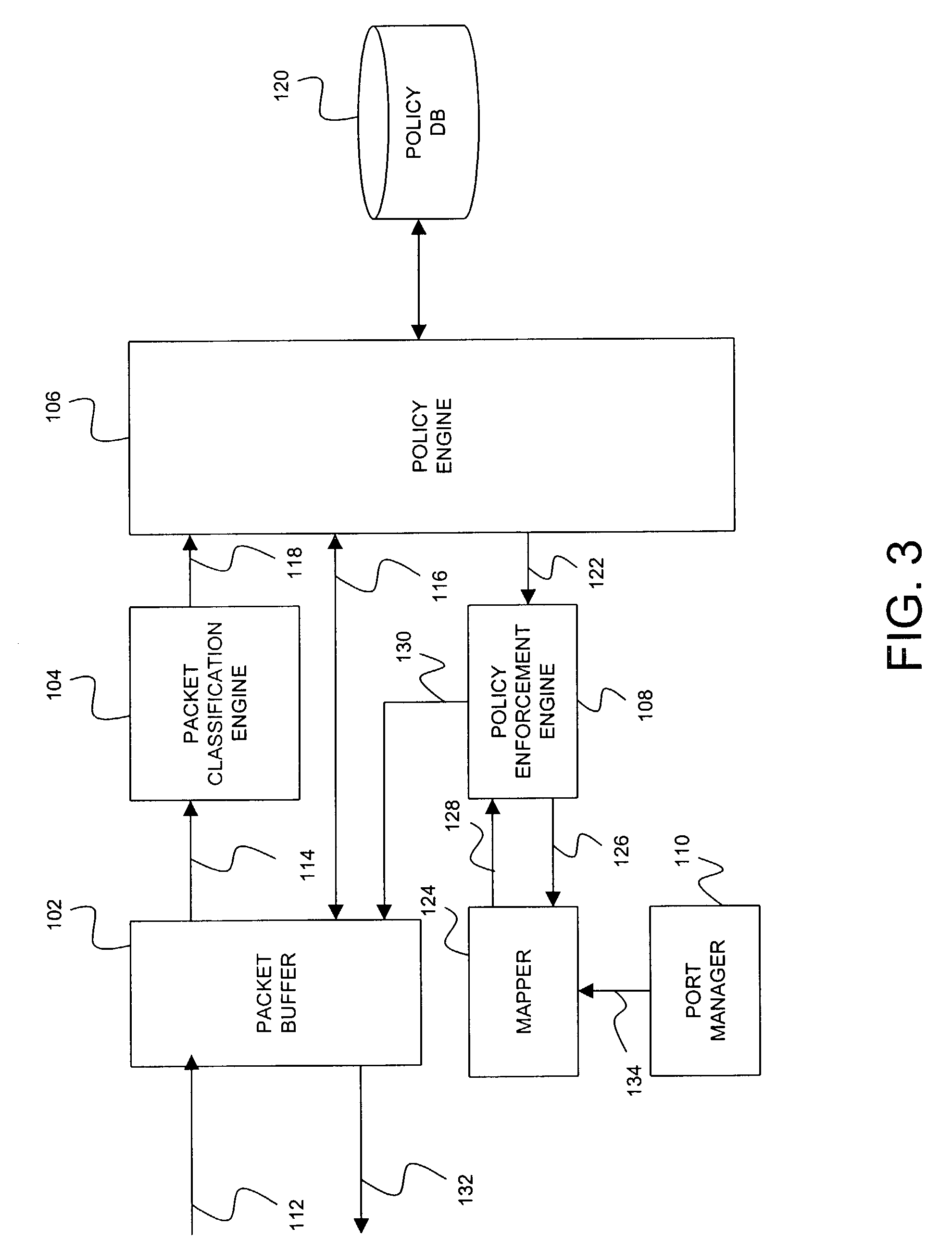
[0024]FIG. 1 is a schematic block diagram of a network environment including a packet switching node 10 according to one embodiment of the invention. The packet switching node may also be referred to as a switch, a data communication node or a data communication switch. The packet switching node 10 includes switching interfaces (also referred to as ports) 14, 16 and 18 interconnected to respective groups of LANs 30, 32, 34, and to one another over data paths 20, 22, 24 via switching backplane 12. The switching backplane 12 preferably includes a switching fabric. The switching interfaces may also be coupled to one another over control paths 26 and 28.

[0025]The switching interfaces 14, 16, 18 forward packets to and from their respective groups of LANs 30, 32, 34 in accordance with one or more operative communication protocols, such as, for example, media access control (MAC) bridging and Internet Protocol (IP) routing. The switching node 10 is shown for illustrative purposes only. In ...


PUM


Abstract

A dynamic queue allocation and de-allocation mechanism for managing traffic flowing through a switching node. If a packet matches conditions of a particular QoS policy rule, a determination is made as to whether a queue associated with the matched QoS policy rule exists on an egress port that is to forward the packet. If such a queue does not exist, a determination is made as to whether enough resources are available for dynamically creating the queue according to the QoS action parameters of the matched QoS policy rule. If the new queue may not be created because of resource limitation, queues of lower priority existing on the port are reclaimed and their resources reassigned to the new queue.

Description

CROSS-REFERENCE OF RELATED APPLICATION(S)[0001]This application claims the benefit of U.S. provisional application No. 60 / 328,159, filed on Oct. 10, 2001, the contents of which are incorporated herein by reference.FIELD OF THE INVENTION[0002]This application relates generally to managing network resources in a network switching node, and more particularly, to dynamic allocation and de-allocation of queues in the node for managing data traffic.BACKGROUND OF INVENTION[0003]Packets received by a network switching node are generally stored in hardware or software queues prior to being forwarded to a destination. Each queue in the node is typically configured by a network administrator prior to its use. For example, the queue may be configured with various parameters available for the particular queue, with an interface type, and with information on the priority of data packets to be stored in the queue.[0004]A drawback with the existing manner of configuring queues is that the process i...

Claims


Application Information

Patent Timeline
IPC IPC(8): H04L12/28H04J3/16H04L12/24H04L12/46H04L12/56H04Q11/04
CPCH04L12/4625H04L41/0893H04L47/10H04L47/20H04L47/2408H04L47/2441H04L47/245H04L47/76H04L47/781H04L47/805H04L47/822H04L49/205H04L49/90H04Q11/0478H04L49/254H04L49/30H04L49/3027H04L2012/5625H04L2012/5678H04L2012/5684H04L41/0894
Inventor MORGAN, DAVID LYNNCLAWSON, STEPHENFREEMAN, JAMES
Owner ALCATEL LUCENT SAS
Why Eureka
Try Eureka