Method and device for vibration control

a vibration control and tool technology, applied in the direction of turning apparatuses, metal-working holders, supports, etc., can solve the problems of affecting the evenness of the workpiece surface, the service life of the tool, and the vibration of the tool, so as to achieve maximum controllability of vibrations

Inactive Publication Date: 2008-03-11
STAFFANSBODA CIE
View PDF28 Cites 28 Cited by
  • Summary
  • Abstract
  • Description
  • Claims
  • Application Information

AI Technical Summary

Benefits of technology

[0019]The idea of embedding, according to the invention, at least one active element in the tool holder implies a minimal modification of the tool holder and at the same time uses the rapidity and the capability of changing dimensions of the active element in an optimal manner. The embedding makes it possible to transfer more efficiently the dimensional change direct to the body of the tool holder and with maximum efficiency.
[0022]The active element according to the invention can be made small. This makes it easy to build the active element into the tool holder when manufacturing the same without any detrimental effect on the mechanical properties of the tool holder. Besides it will be possible later to mount the element in existing tool holders.
[0023]Moreover, the mounting will be flexible since the active element may be mounted with an optional orientation. Consequently it will be possible to achieve maximum controllability for vibrations of practically any direction whatever.

Problems solved by technology

The chip-forming process is largely stochastic and the excitation results in tool vibrations and noise.
In addition to thus causing problems in the working environment, the dynamic motion also affects the evenness of the surface of the workpiece and the service life of the tool.
It is known that the vibration problem is closely connected with the dynamic stiffness in the construction of the machine and the material of the workpiece.
In many cases, it is the lack of dynamic stiffness of the tool holder that is a main problem.
The actuator is operated in such manner that the countervibrations interfere destructively with the tool vibrations.
This construction is unwieldy since the actuator is a comparatively large component which must be mounted on a suitable surface of the tool holder.
Moreover, the directive efficiency is not quite distinct.
In fact, the modification counteracts the purpose of the construction by reducing the stiffness of the tool holder in the most important directions, above all vertically, which in itself causes a greater vibration problem, or alternatively means that the dimensions of the tool holder must be increased significantly in order to maintain the stiffness.

Method used


Image

  • Method and device for vibration control
  • Method and device for vibration control
  • Method and device for vibration control

Examples


Embodiment Construction

[0030]A basic object of the invention is to counteract the arising of vibrations causing noise, wear and uneven surfaces in connection with cutting of a workpiece. The casual relation for the arising of vibrations in cutting has been described above. A correctly performed vibration control according to the invention obviates the problems and results in an excellent surface finish.

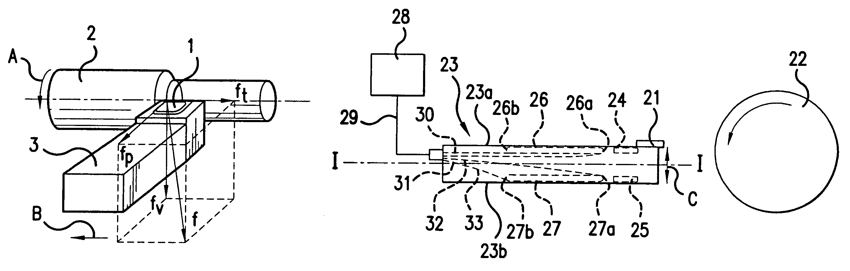
[0031]FIG. 1 shows an example of forces to which a tool 1, in this case a turning insert, is exposed owing to the working of a workpiece 2. The tool 1 is supported by a tool holder 3, with which the tool 1 is rigidly connected. The workpiece 2 rotates in the direction of arrow A. The tool holder 3 moves in a direction of feed indicated by arrow B. The rotation of the workpiece 2 and the motion of the tool holder 3 together generate a resultant force as illustrated by arrow f. The resultant force f can be divided into components ff, fp and fv. As appears from FIG. 1, the dominating component is fv which desi...


PUM

PropertyMeasurementUnit
A.C. voltageaaaaaaaaaa
distanceaaaaaaaaaa
dimensionaaaaaaaaaa

Abstract

A device and method for vibration control in a machine for cutting, said machine comprising a cutting tool supported by a tool holder. The device comprises a control unit and converting means which are connectible to the control unit and comprise a vibration sensor and an actuator. The actuator comprises an active element which converts an A.C. voltage supplied by the control unit to the actuator into dimensional changes. Said active element is adapted to be embedded in the body of the tool holder and in such manner that said dimensional changes impart bending to the body of the tool holder.

Description

[0001]This application is a continuation of U.S. patent application Ser. No. 09 / 838,328 filed on Apr. 20, 2001 now abandoned which is a Continuation of PCT International Application No. PCT / SE99 / 01883 filed on Oct. 19, 1999, which was published in English and designated the United States and on which priority is claimed under 35 USC §120 and which application claims priority of Application No. 9803605-6 filed in Sweden on Oct. 22, 1998 under 35 USC §119, the entire contents of all are hereby incorporated by reference.BACKGROUND OF THE INVENTION[0002]1. Field of the Invention[0003]The present invention relates to a method and a device for vibration control, and more specifically a method, a device and a tool holder for vibration control in cutting.[0004]2. Background Art[0005]In cutting, such as turning, drilling, milling or planing, dynamic motion arises between the tool and the workpiece. The motion is largely due to the fact that the chip-forming process, i.e. the removal of the g...

Claims


Application Information

Patent Timeline
Patent Type & Authority Patents(United States)
IPC IPC(8): B23Q17/12B23B27/00B23B29/00B23Q15/12B23B1/00B23B29/12B23B37/00B23Q3/12B23Q5/22B23Q11/00
CPCB23B27/002B23Q11/0032Y10S82/904Y10T82/2585Y10T82/2595Y10T82/10Y10T82/2533Y10T82/2502Y10T409/304312Y10T408/76
Inventor CLAESSON, INGVARLAGO, THOMASHAKANSSON, LARS
Owner STAFFANSBODA CIE
Why Eureka
Try Eureka