
High temperature flexible pipe joint

a flexible pipe and high temperature technology, applied in the direction of adjustable joints, drilling pipes, mechanical equipment, etc., can solve the problems of local ruptures in the elastomer surface, temperature of production fluid substantially exceeding 180° f, and severe deformation of the service life of the conventional flexible pipe joint. , to achieve the effect of high temperature flexible pipe joints and high temperature flexible pipes

Active Publication Date: 2008-03-11
WELLS FARGO BANK NAT ASSOC +1
View PDF63 Cites 62 Cited by
  • Summary
  • Abstract
  • Description
  • Claims
  • Application Information

AI Technical Summary

Benefits of technology

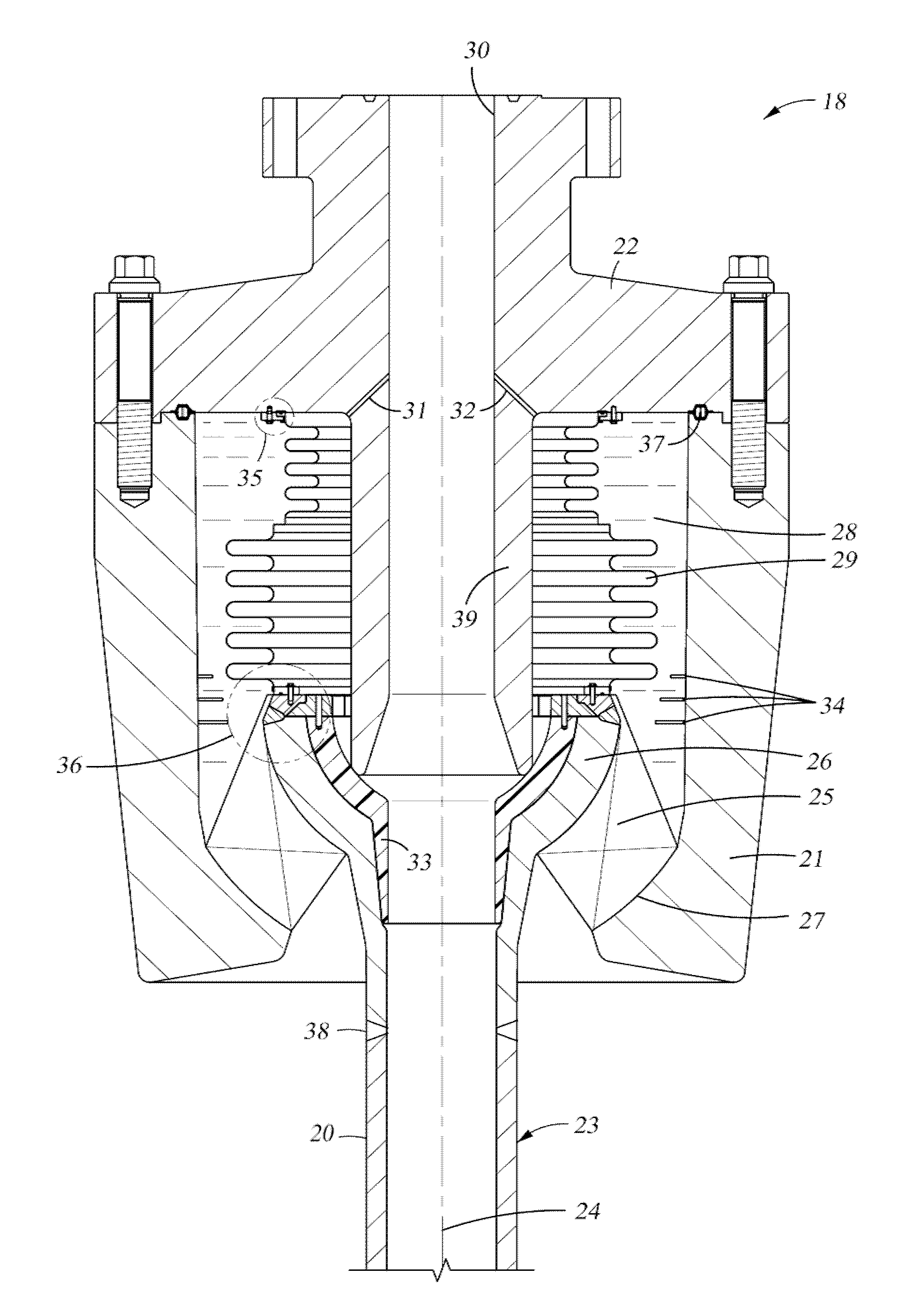
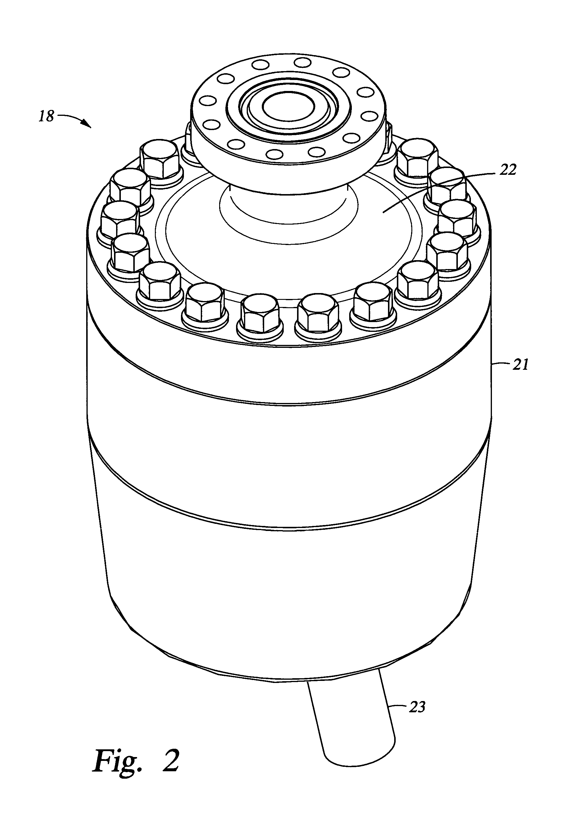
The invention provides a high temperature flexible pipe joint that can operate over a long service life. It includes a body, an extension pipe, and a laminated elastomeric flex element coupling the extension pipe to the body. The flex element has alternate elastomer layers and reinforcement layers, and is designed to shift strain from the inner layers to the outer layers. The joint also includes a heat shield and the extension pipe is made of low heat conductivity metal in the vicinity of the flex element. The technical effects of the invention are improved flexibility, durability, and resistance to high temperatures, making it suitable for use in extreme environments.

Problems solved by technology

For example, if the elastomer were exposed to high-pressure production fluid containing low molecular weight gasses such as methane, explosive decompression could occur upon sudden release of the high pressure, causing gas molecules captured in the elastomer to expand and cause local ruptures in the elastomer surface.
However, the planned depths of the wells below the seabed and the desired high flow rates would cause the temperature of the production fluid to substantially exceed 180° F.
This would cause the service life of the conventional flexible pipe joint to be severely degraded.

Method used


Image

  • High temperature flexible pipe joint
  • High temperature flexible pipe joint
  • High temperature flexible pipe joint

Examples


Embodiment Construction

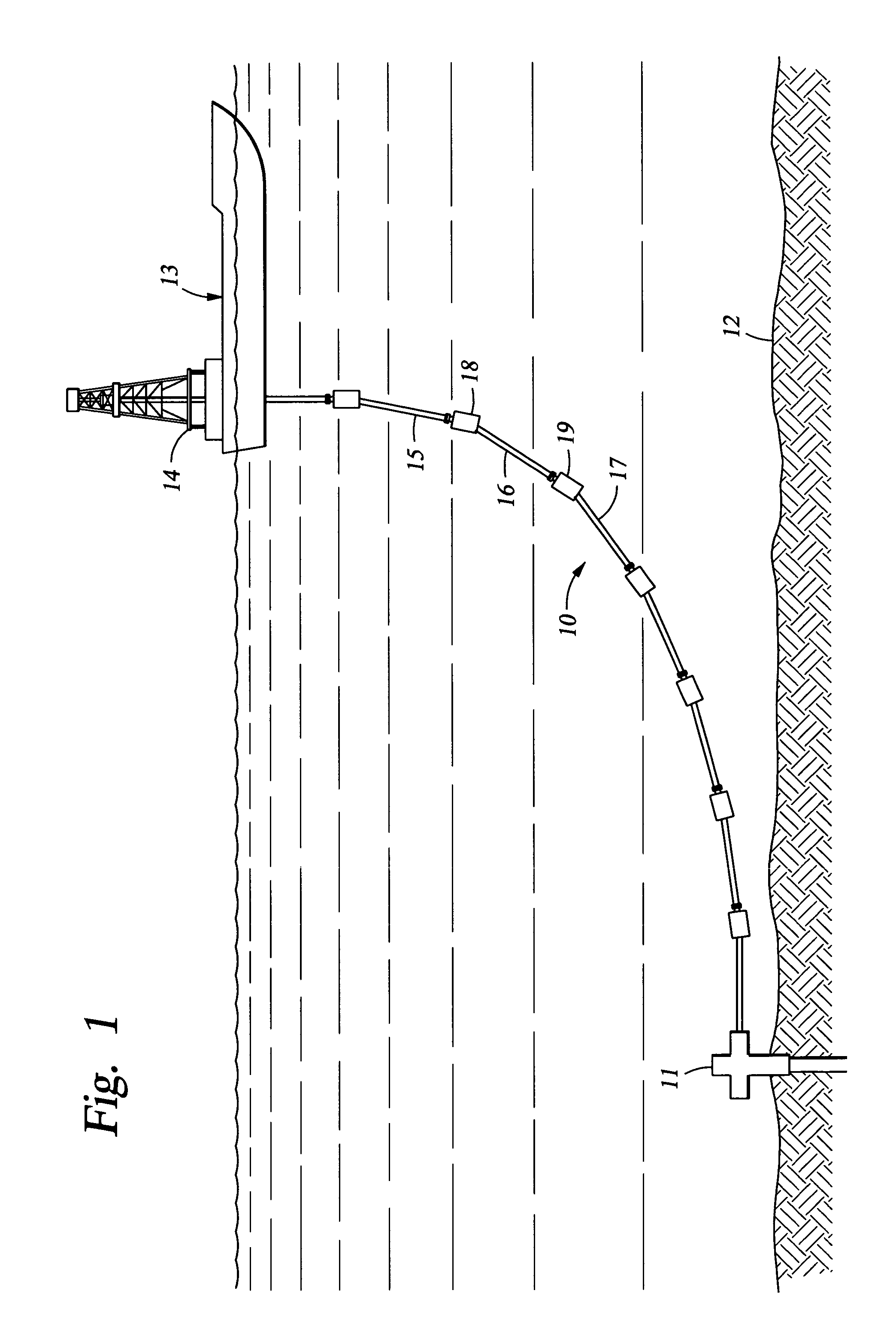
[0029]With reference to FIG. 1, there is shown a steel catenary riser (SCR) generally designated 10 for conveying production fluid such as oil or gas from a well head 11 on the sea bed 12 to a floating production storage and offloading facility (FPSO) 13. The FPSO 13 is essentially a supertanker provided with a derrick 14 capable of deploying and retrieving drill strings and risers to and from the seabed 12. The steel catenary riser 10 is comprised of steel pipe sections e.g. 15, 16, 17 interconnected by flexible pipe joints 18, 19.

[0030]For a well that has been drilled very far below the seabed 12, the production fluid issuing from the wellhead 11 may considerably exceed 180° F. (82° C.) especially for very high flow rates. For example, the maximum production fluid temperatures expected for high flow rates from deep offshore wells currently being drilled are generally in the range of 240° F. (115° C.) to 265° F. (130° C.), and it is not inconceivable that future offshore wells coul...


PUM


Abstract

For continuous high temperature operation over a service life in excess of twenty years, a flexible pipe joint includes various features that tend to reduce the temperature of the load-bearing flex element or reduce strain in the warmer elastomeric layers of the flex element. These features include a heat shield of low heat conductivity material integrated into the inner profile of the pipe extension and interposed between the central bore of the pipe joint and the flex element, low heat conductivity metal alloy components between the hot production fluid and the flex element, high temperature resistant elastomer at least in the warmest inner elastomer layer of the flex element, and a flex element constructed to shift strain from the warmer inner elastomer layers to the colder outer elastomer layers by providing greater shear area, different layer thickness, and / or higher elastic modulus elastomer for the warmer inner elastomer layers.

Description

BACKGROUND OF THE INVENTION[0001]1. Field of the Invention[0002]The present invention relates to a flexible pipe joint for subsea risers and pipelines, and in particular, such a flexible pipe joint that is capable of long-term operation when subjected to temperatures greater than about 180° F. (82° C.).[0003]2. Description of the Related Art[0004]Offshore production facilities typically use risers constructed of rigid pipe sections and flexible joints for conveying production fluid such as oil or gas from a well on the seabed to a floating offshore production platform. This construction, for example, permits a pipeline to be laid under water and then raised for connection to the offshore production platform.[0005]Typically, a flexible pipe joint has a laminated elastomeric flex element including alternating layers of elastomer and steel plates. The elastomer is bonded to the steel plates and the steel plates are encapsulated in the elastomer. The elastomer is typically vulcanized na...

Claims


Application Information

Patent Timeline
Patent Type & Authority Patents(United States)
IPC IPC(8): F16L51/02F16L27/10F16L27/103F16L27/11
CPCE21B17/085F16L27/103F16L27/11
Inventor MOSES, CHARLES JHOGAN, MICHAEL EMOSES, PHILIP SPOTTORFF, TODD MSPICER, CARL C
Owner WELLS FARGO BANK NAT ASSOC
Learn More