Dynamical instrument for machining

Inactive Publication Date: 2008-03-11
FOSTER-MILLER
View PDF15 Cites 31 Cited by
  • Summary
  • Abstract
  • Description
  • Claims
  • Application Information

AI Technical Summary

Benefits of technology

[0011]It is a further object of this invention to provide such a dynamical instrument for machining which provides a real-time status of the state of a bit as the workpiece is being machined.
[0012]It is a further object of this invention to provide such a dynamical instrument for ma

Problems solved by technology

Other machine shops may manufacture parts which are more expensive, typically costing hundreds or thousands of dollars to manufacture.
The parts produced by large machine shops are usually complex and must conform to strict specification requirements provided by the customer.
Post inspection of the workpiece surface finish is requ

Method used


Image

  • Dynamical instrument for machining
  • Dynamical instrument for machining
  • Dynamical instrument for machining

Examples


Embodiment Construction

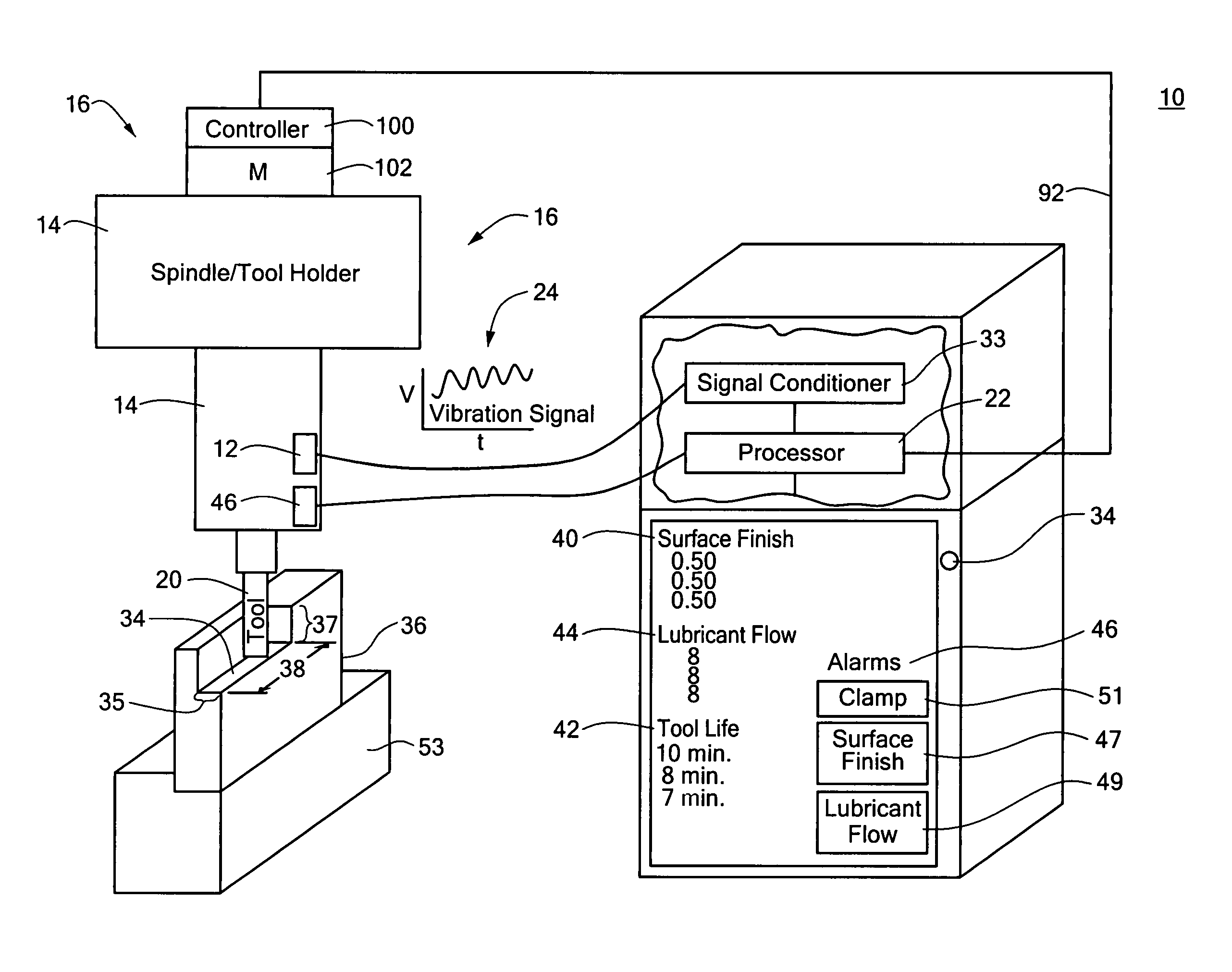
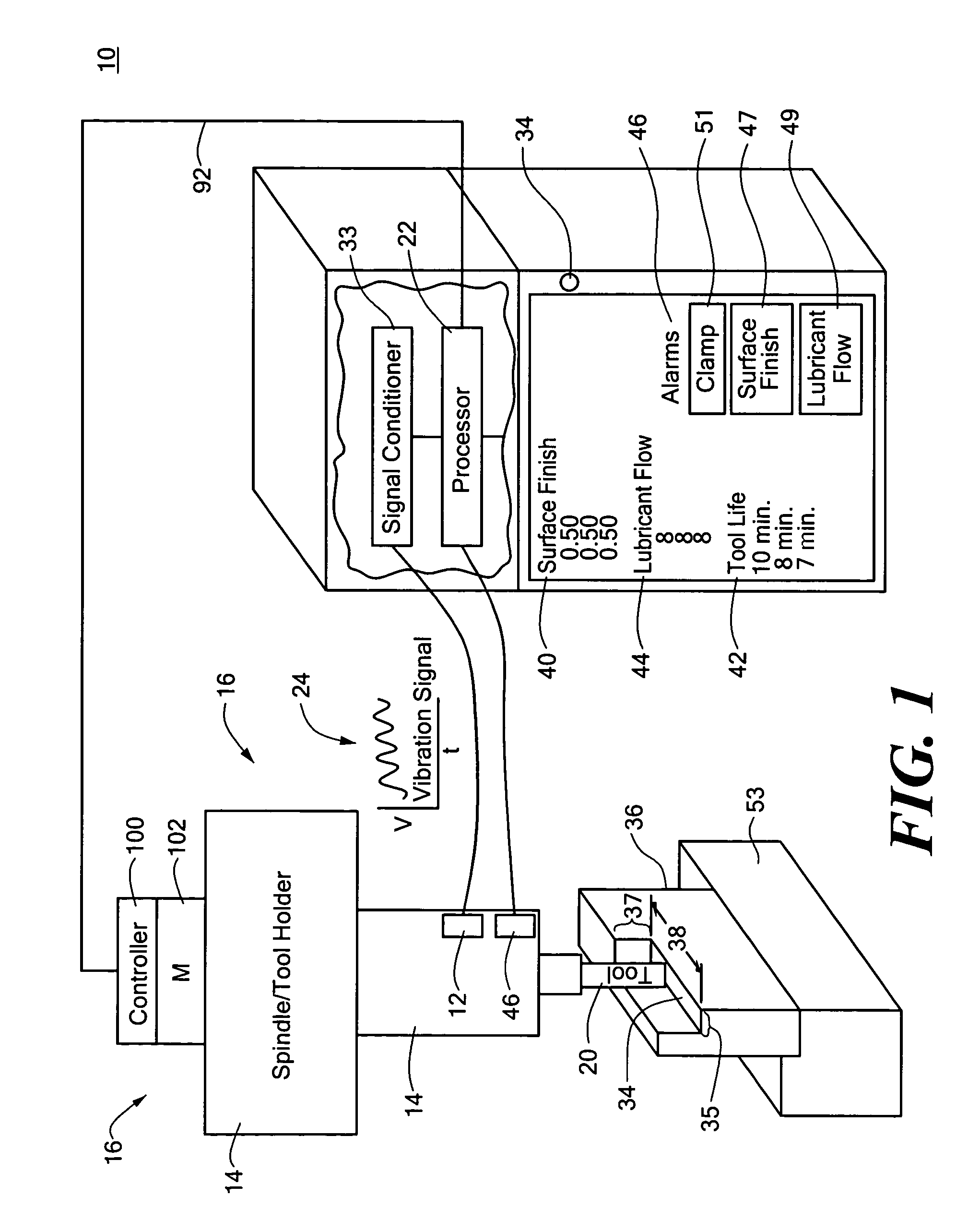
[0047]Aside from the preferred embodiment or embodiments disclosed below, this invention is capable of other embodiments and of being practiced or being carried out in various ways. Thus, it is to be understood that the invention is not limited in its application to the details of construction and the arrangements of components set forth in the following description or illustrated in the drawings.

[0048]As explained in the Background section above, conventional methods for machining do not provide a machine operator with an objective dynamic measurement of the surface finish of a workpiece as it is being manufactured. Therefore, operators must rely on subjective visual, auditory, and / or vibration cues to adjust spindle speed, depth of cut, and rate of advance of the cutting tool to insure proper surface finish. Conventional methods also do not provide an operator with dynamic information to determine whether a machine tool is worn or damaged, whether proper cooling / lubricant flow is ...


PUM

PropertyMeasurementUnit
Timeaaaaaaaaaa
Lengthaaaaaaaaaa
Surfaceaaaaaaaaaa

Abstract

A dynamical instrument for machining comprising a sensor responsive to a non-rotating part of a machine proximate the tool of the machine for outputting a vibration signal, and a processor responsive to the sensor output configured to calculate a plurality of signature quantities which characterize the dynamics of the vibration signal and correlate the signature quantities to detect parameters associated with the operation of the machine.

Description

RELATED APPLICATIONS[0001]This invention was made with U.S. Government support under Contract No. 50-DKNB-6-90107 and awarded by the Department of Commerce National Institute of Standards and Technology (NIST). The Government may have certain rights in the subject invention.FIELD OF THE INVENTION[0002]This invention relates generally to machine tools.COMPUTER PROGRAM LISTING APPENDIX[0003]A computer program listing appendix is filed herewith on compact disk. The material on the compact disk is hereby incorporated by reference. Two identical compact disks have been submitted. Each compact disk contains one file entitled source.txt. The two disks were created on Feb. 28, 2003.BACKGROUND OF THE INVENTION[0004]Sone machine shops typically operate machines, such as milling machines, lathes, and the like, at reduced rates, typically one-third to one-half the full capacity, in order to avoid breaking the tool when manufacturing an inexpensive part, e.g., the bit may cost fifteen dollars bu...

Claims


Application Information

Patent Timeline
IPC IPC(8): B23C3/00G01N29/14G05B19/406
CPCB23Q17/0971G05B19/406G05B2219/37217G05B2219/37242G05B2219/37402G05B2219/37432Y10T409/303752Y10T409/307224Y10T408/76Y10T82/2595Y10T409/304312Y10T409/30952Y10T409/101113G05B2219/37435
Inventor HILL, WAYNE S.BARCK, BRUCE N.
Owner FOSTER-MILLER
Why Eureka
Try Eureka