
Intraocular lens for correcting presbyopia

a technology of intraocular lens and presbyopia, which is applied in the field of intraocular lens for correcting vision, can solve the problems of degrading vision, peripheral vision remains intact, and reading and driving vision can be los

Inactive Publication Date: 2008-03-11
MINU
View PDF21 Cites 47 Cited by
  • Summary
  • Abstract
  • Description
  • Claims
  • Application Information

AI Technical Summary

Benefits of technology

[0027]Still yet a further object of the present invention is to provide a substantially ring shaped, doughnut shaped or substantially semi-ring shaped IOL that can correct near vision caused by presbyopia, while not effecting far vision.

Problems solved by technology

However, an eye can have a disease known as macular degeneration which can greatly degrade vision.
Thus, reading and driving vision can be lost, while peripheral vision remains intact.
However, problems can arise when microkeratomes are used for cutting the cornea.
First, irregular keratectomies or perforations of the eye can result.
Second, the recovery of vision can be rather prolonged.
By separating the layers in the bottom two-thirds of the stromal portion, it is difficult to access the separated area to insert the inlay and virtually impossible to change or modify the inlay without another extensive surgical procedure.
Other conventional methods that have been employed specifically to correct presbyopia have been unsuccessful.
However, because only certain amount of cornea can be ablated without the remaining cornea becoming unstable or experiencing outbulging (ectasia), this technique is not especially effective in correcting very high myopia.
Also, these conventional implants, while correcting a refractive error of the patient, also distort the normal vision of the patient.
Use of these instruments may result in damage or imprecision in the cut or formation of the desired area in which the implant is placed.
Additionally, these conventional techniques do not include determination and testing of an appropriate implant for correcting a refractive error of a particular patient.
Also, prior methods for the treatment of presbyopia have been unsuccessful.
However, because the disc covered the center area around the visual axis, the patient's farsighted vision was blurred by the inlay.

Method used


Image

  • Intraocular lens for correcting presbyopia
  • Intraocular lens for correcting presbyopia
  • Intraocular lens for correcting presbyopia

Examples


Embodiment Construction

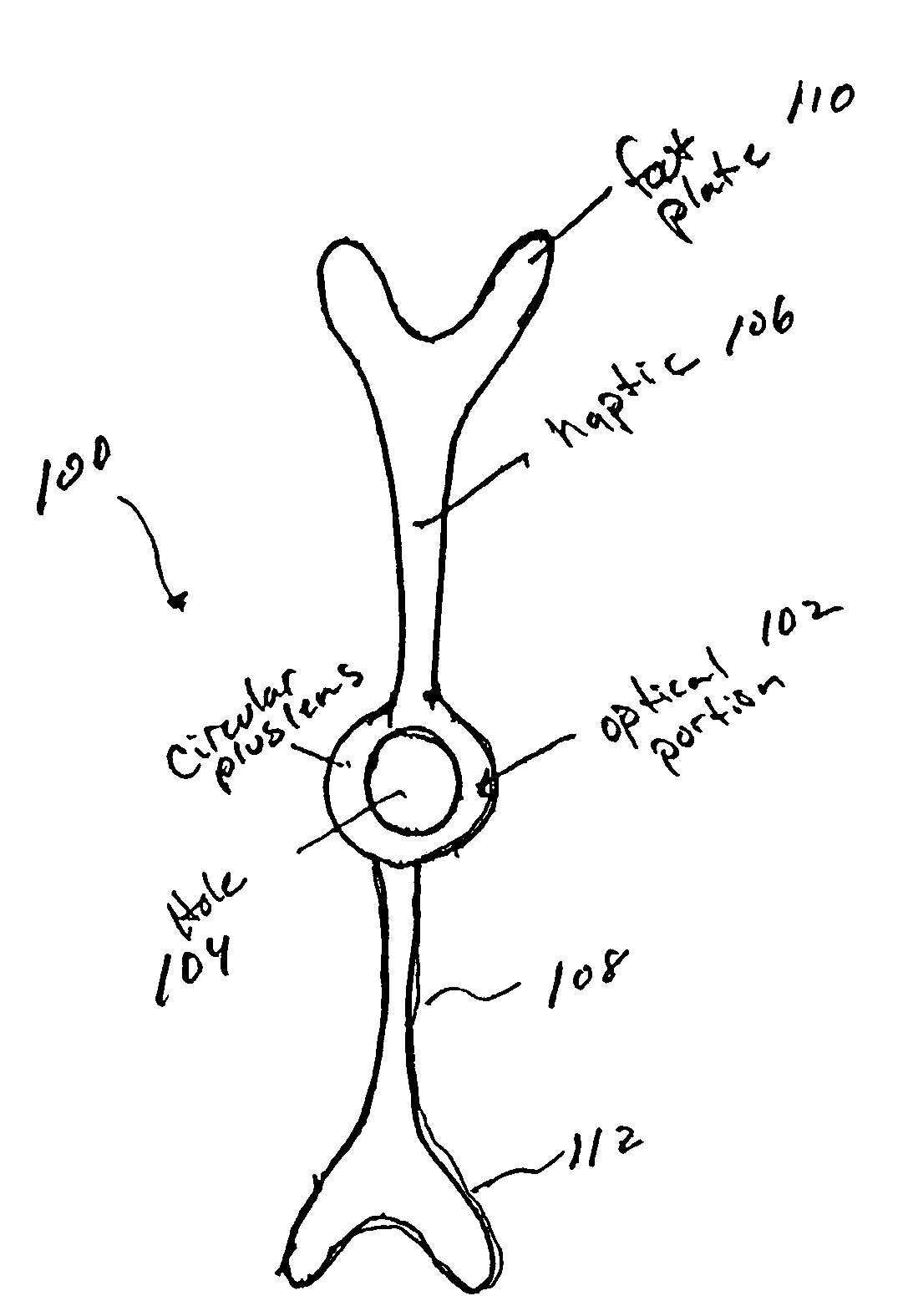
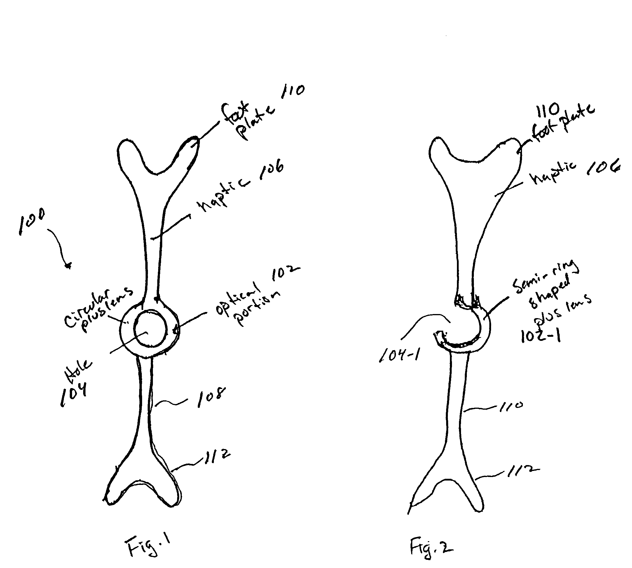
[0048]As shown in FIGS. 1 and 2, a lens system 100 according to an embodiment of the present invention includes an optical portion 102 for use in correcting presbyopia. In this example, the optical portion 102 is preferably circular, substantially circular or doughnut-shaped to act as a plus lens, but can be any shape desired. For instance, as shown in FIG. 2, the optical portion 102-1 can be semi-circularly shaped or crescent shaped. The optical portion 102 includes an opening 104 that can be centered or substantially centered in the optical portion 102, or can be located anywhere in the optical portion 102 as appropriate. Similarly, the optical portion 102-1 can be shaped such that the opening 104-1 is centered with respect to the optical portion 102-1 or such that the opening 104-1 is off-centered by a desired distance.

[0049]The optical portion 102 (102-1), which can also be referred to as a lens, is preferably made of synthetic material, organic material, or a combination of bot...


PUM


Abstract

An intraocular lens for modifying the refractive abilities of a natural lens or an existing artificial lens in an eye to correct for vision disorders such as presbyopia, myopia, hyperopia or astigmatism. Specifically, the lens system can be configured so that it does not effect far vision, while effecting near vision using a plus lens to correct for presbyopia. The lens system includes a lens portion and fastening members, with the lens portion being movably secured to at least one of the fastening members so that the position of the lens portion can be modified with respect to the optical axis, and the overall length of the lens system can be increased or decreased.

Description

[0001]This application claims benefit under 35 U.S.C. § 119(e) from U.S. Provisional Patent Application Ser. No. 60 / 461,194, filed on Apr. 9, 2003, the entire contents of which are incorporated herein by referenceCROSS-REFERENCE TO RELATED APPLICATIONS[0002]This application is related to U.S. Pat. No. 6,197,057 to Peyman et al. entitled “LENS CONVERSION SYSTEM FOR TELEDIOPTIC OR DIFFRACTIVE CONFIGURATIONS”, and copending U.S. patent application Ser. No. 10 / 356,730 entitled “SUBEPITHILIAL IMPLANT AND METHOD OF TREATMENT OF PRESBYOPIAN AND OTHER REFRACTIVE ERRORS”, the entire contents of both of which are incorporated herein by reference.BACKGROUND OF THE INVENTION[0003]1. Field of the Invention[0004]The present invention generally relates to a lens system for correcting vision in the eye. More specifically, the present invention generally relates to an intraocular lens system (IOL), which can be implanted in the anterior or posterior chambers of the eye in place of or in addition to ...

Claims


Application Information

Patent Timeline
IPC IPC(8): A61F2/16
CPCA61F2/1602A61F2/1613A61F2/1648A61F2250/0053A61F2/1651
Inventor PEYMAN, GHOLAM A.
Owner MINU
Learn More