Power amplifying apparatus using asymmetric power drive

a power amplifier and power drive technology, applied in amplifiers, amplifiers with coupling networks, amplifiers with semiconductor devices/discharge tubes, etc., can solve problems such as serious problems, low current level of peaking amplifiers, and inability of doherty amplifiers to generate the desired maximum output power, and achieve optimal linearity and high efficiency

Active Publication Date: 2008-03-11
SAMSUNG ELECTRONICS CO LTD
View PDF11 Cites 40 Cited by
  • Summary
  • Abstract
  • Description
  • Claims
  • Application Information

AI Technical Summary

Benefits of technology

[0016]It is, therefore, an object of the present invention to provide a Doherty amplifier using an asymmetric power drive, to thereby achieve optimized linearity while maintaining high efficiency.

Problems solved by technology

In this case, a carrier amplifier is biased as a class AB, and a peaking amplifier a class C. Since the peaking amplifier has a lower bias than that of the carrier amplifier, it is problematic that the current level of the peaking amplifier is always lower than that of the carrier amplifier depending on a power level.
As a result, a load modulation (a phenomenon in which load impedance of the front end of a current source varies with an amplitude of current generated from the current source) occurs and, further, serious problems are caused in the Doherty operation.
As a result, the Doherty amplifier is not able to generate a desired maximum output power.

Method used


Image

  • Power amplifying apparatus using asymmetric power drive
  • Power amplifying apparatus using asymmetric power drive
  • Power amplifying apparatus using asymmetric power drive

Examples


Embodiment Construction

[0044]Hereinafter, preferred embodiments of the present invention will be described in detail with reference to the accompanying drawings.

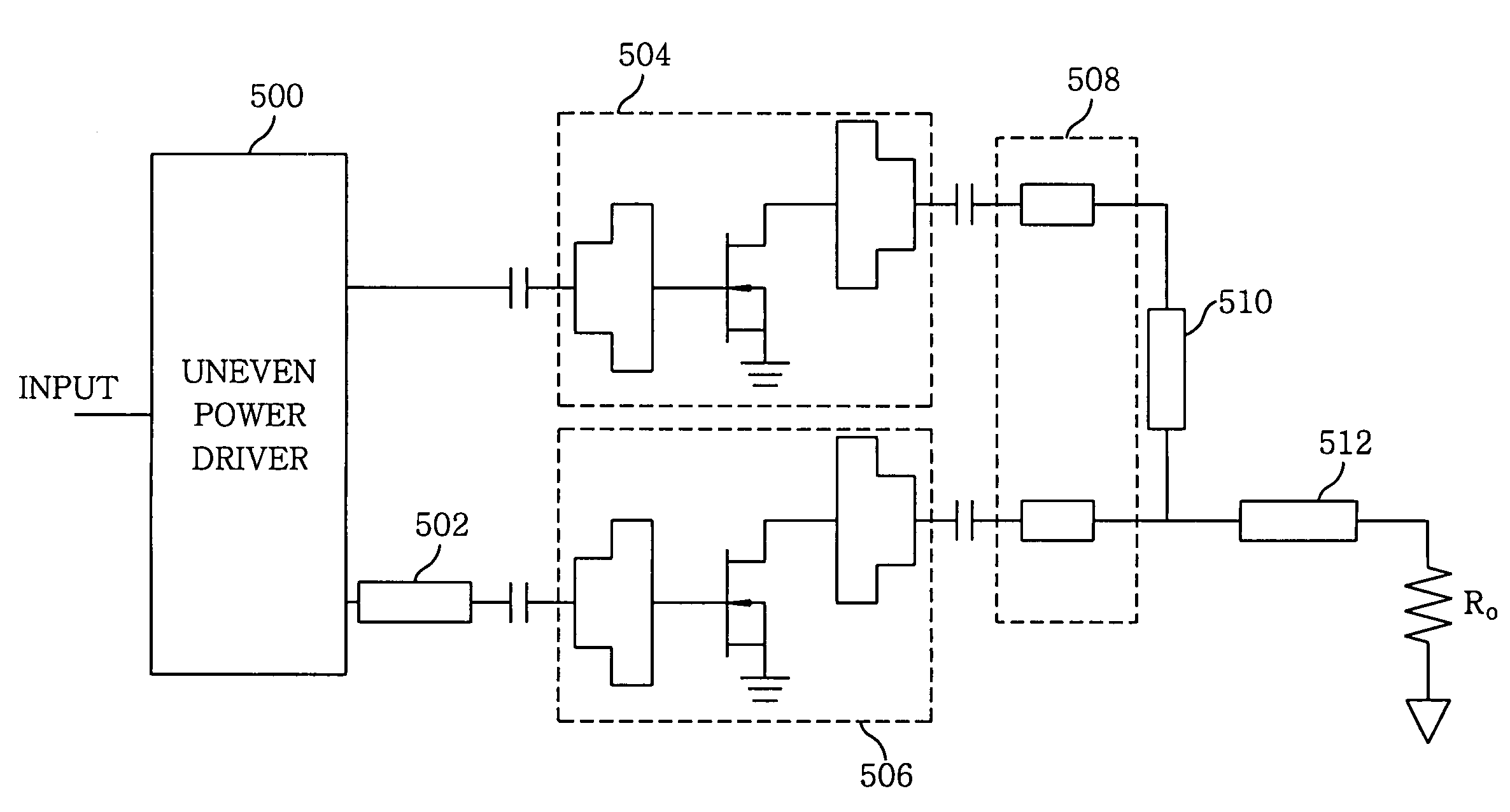
[0045]FIG. 5 offers a block diagram of an N-way (in case of N=2) power amplifying apparatus using an asymmetric power drive in accordance with a preferred embodiment of the present invention. The power amplifying apparatus shown in FIG. 5 includes an asymmetric power driver 500, a transmission line 502, a carrier amplifier 504 and a peaking amplifier 506 connected in parallel, an offset line 508, a first quarter-wave transmission line 510 and a second quarter-wave transmission line 512.

[0046]The carrier amplifier 504 forms a Doherty amplifier together with the peaking amplifier 506. The carrier and the peaking amplifier 504 and 506 have the same input and output matching circuits, respectively.

[0047]The asymmetric power driver 500 performs an asymmetric power drive to the carrier and the peaking amplifier 504 and 506. Preferably, more power is sup...


PUM


Abstract

A power amplifying apparatus includes a Doherty amplifier having a carrier amplifier and a peaking amplifier connected in parallel, each having an input / output matching circuit and an asymmetric power driver for driving the carrier amplifier and the peaking amplifier using an asymmetric power driver.

Description

FIELD OF THE INVENTION[0001]The present invention relates to a high efficiency and linearity power amplifying apparatus; and, more particularly, to a power amplifying apparatus using an asymmetric power drive, which employs a microwave Doherty amplifier.BACKGROUND OF THE INVENTION[0002]As well-known in the art, a Doherty power amplifier has a structure of a carrier and a peaking amplifier connected in parallel by using a quarter-wave transformer (λ / 4 line). Further, the Doherty amplifier is driven by a symmetrical power driving method in which the peaking amplifier controls a load impedance of the carrier amplifier by increasing the amount of current supplied to the load from the peaking amplifier as the power level is increased, thereby improving efficiency.[0003]A microwave Doherty amplifier has been used in an amplitude modulation (AM) transmitter of a broadcasting apparatus using a high-power low-frequency (LF) vacuum tube or a medium frequency (MF) vacuum tube. There have been ...

Claims


Application Information

Patent Timeline
Patent Type & Authority Patents(United States)
IPC IPC(8): H03F3/68
CPCH03F1/0288H03F3/602H03F2200/198H03F2200/387H03F2200/451H03F3/60
Inventor KIM, BUMMANCHA, JEONGHYEONKIM, JANGHEONKIM, ILDU
Owner SAMSUNG ELECTRONICS CO LTD
Why Eureka
Try Eureka