Register window system and method that stores the next register window in a temporary buffer

a register window and buffer technology, applied in the field of register window system and method, can solve the problems of inability to supply operands, inability to execute instructions which are to be executed subsequently to save instructions or restore instructions, and difficulty in high-speed supply of operands to arithmetic operation units, so as to reduce hardware resources and improve data read throughput

Inactive Publication Date: 2008-03-11
FUJITSU LTD
View PDF13 Cites 5 Cited by
  • Summary
  • Abstract
  • Description
  • Claims
  • Application Information

AI Technical Summary

Benefits of technology

[0028]With the foregoing problems in view, it is an object of the present invention to reduce hardware resources and to improve data read throughput in an information processing apparatus which employs register windows and the out-of-order execution method.
[0049]As described so far, according to the present invention, the arithmetic operation unit is connected in such a manner that it can read data from the current register and the replacing buffer. When the arithmetic operation unit decodes a window switching instruction such as a SAVE instruction and a RESTORE instruction, the control unit performs control such that data of a register window, which is next to be held in the current register after execution of the switching instruction, is read from a master register, and is then stored in the replacing buffer. Inconsequence, it becomes possible for the arithmetic operation unit to read data, which is next to be held in the current register after execution of the window switching instruction, from the replacing buffer before actual execution of the window switching instruction, thereby reliably executing an instruction which uses data of the above mentioned register window.
[0050]Therefore, differing from the previous apparatus, it is no longer necessary to pre-read the preceding and the following register windows of the current register window, a total of three registers windows, and instructions are executable in the out-of-order method. Thus, the capacity (hardware resource) of a register which is required to execute an instruction following a window switching instruction before actual execution of the window switching instruction, is reduced.
[0051]In consequence, throughput at data reading from the current register and the replacing buffer for instruction execution by the arithmetic operation unit is improved.
[0052]In addition, since hardware resources are reduced, an implement area for registers is reduced, and power consumption is also reduced.

Problems solved by technology

Generally speaking, a register window with a large number of windows needs a considerably large register file (eight windows need 136 registers), and thus it becomes difficult to supply operands to an arithmetic operation unit in high speed.
In consequence, when an SAVE instruction or a RESTORE instruction is executed, it becomes impossible to supply operands necessary in the subsequent instruction from the WRF 102, which is a new problem.
However, instructions which are to be executed subsequently to a SAVE instruction or a RESTORE instruction cannot be executed until the window after being subjected to the SAVE / RESTORE operations is transferred to the WRF 102, even if such instructions become executable.
Such limitation will considerably deteriorate the performance of information processing apparatuses which employ the out-of-order instruction execution method, in which apparatuses the number of instructions concurrently issued is large.
Accordingly, the above-mentioned limitation that the order of execution of instruction cannot be changed when SAVE instructions and RESTORE instructions appear will cause a phenomenon that every when a SAVE instruction or a RESTORE instruction appears the out-of-order processing mechanism does not function, thereby causing significant deterioration in the performance.

Method used


Image

  • Register window system and method that stores the next register window in a temporary buffer
  • Register window system and method that stores the next register window in a temporary buffer
  • Register window system and method that stores the next register window in a temporary buffer

Examples


Embodiment Construction

)

[0063]Referring to the relevant drawings, one preferred embodiment of the present invention will now be described.

[1] One Preferred Embodiment

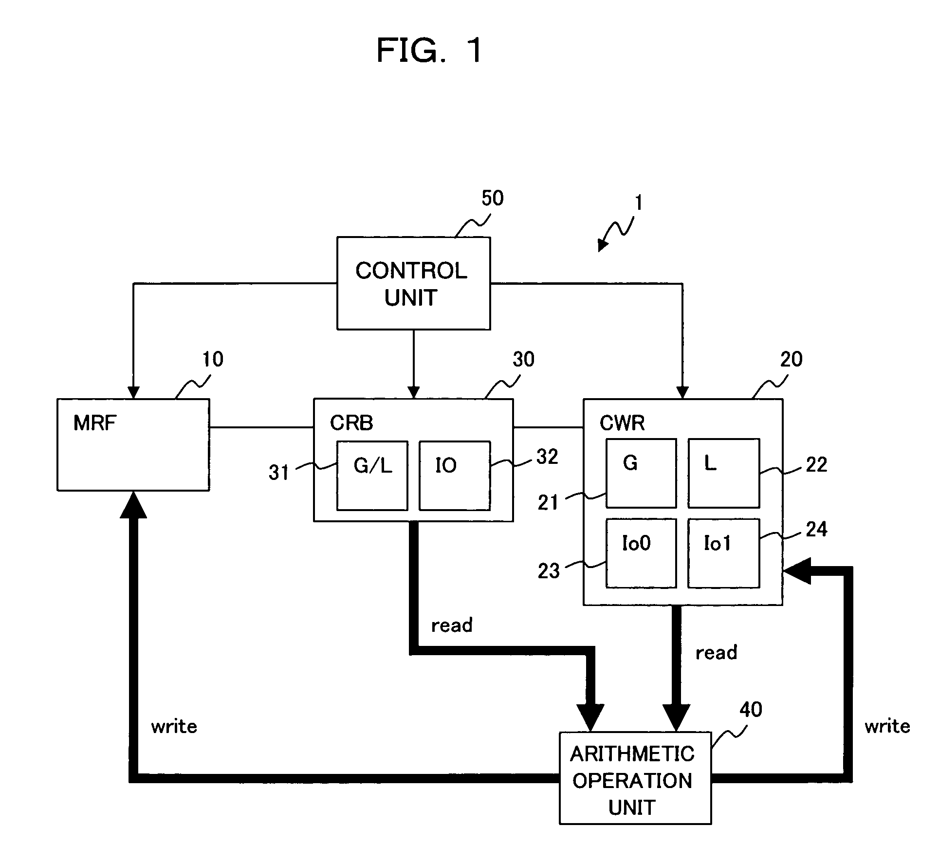
[0064]First of all, referring to the block diagram of FIG. 1, a description will be made hereinbelow of a construction of an information processing apparatus according to one preferred embodiment of the present invention. As shown in FIG. 1, the present information processing apparatus 1 includes: a Master Register File (master register; MRF) 10; a Current Window Register (current register; CWR) 20, a Current window Replace Buffer (replacing buffer; CRB) 30; an arithmetic operation unit 40; and a control unit 50.

[0065]The master register file (hereinafter called “MRF”) 10 includes more than one register windows each storing data therein, and has a ring-like register file A as shown in FIG. 5. That is, a register file A, as an MRF 10, is a register file of an overlap register window type, in which register windows W0 through W7 are linked in a...


PUM


Abstract

The present apparatus reduces hardware resources and improves data read throughput in an information processing apparatus employing the out-of-order instruction execution method. The apparatus includes: an arithmetic operation unit which executes a window switching instruction and an instruction relating to data stored in the current register or data held in the replacing buffer; and a control unit which transfers, if a window switching instruction is decoded at execution of the window switching instruction by the arithmetic operation unit, data of the register window which is to be specified by the current window pointer upon completion of execution of the window switching instruction, to the replacing buffer.

Description

BACKGROUND OF THE INVENTION[0001]1. Field of the Invention[0002]The present invention relates to an art for making it possible to change the order in which instructions are executed in an information processing apparatus with architecture having register windows, which information processing apparatus employs the out-of-order instruction execution method. The changing in the order of instruction execution is performed, irrespectively of register window switching.[0003]2. Description of the Related Art[0004]Some of previous information processing apparatuses (RISC: Reduced Instruction Set Computer) employing architecture of a reduced instruction set type, have more than one register set (hereinafter called “register window”), thereby making it unnecessary to save / return registers, caused at the time of calling / returning of a subroutine, on a memory stack.[0005]Register windows are linked in a ring-like form, and their management is performed using register window numbers (hereinafter...

Claims


Application Information

Patent Timeline
Patent Type & Authority Patents(United States)
IPC IPC(8): G06F9/44
CPCG06F9/30043G06F9/30127G06F9/3851B63C9/08B63C2009/0023A63B2208/03A63B2225/605
Inventor KAN, RYUJIYAMASHITA, HIDEOYOSHIDA, TOSHIO
Owner FUJITSU LTD
Why Eureka
Try Eureka