Placing tool with means for controlling placing processes

a technology of controlling process and positioning tool, which is applied in the direction of measuring/indicating equipment, shaping safety devices, electrical/magnetic measuring arrangements, etc., can solve the problem of not being able to ensure through inspection whether the riveting operation has then proceeded without faul

Inactive Publication Date: 2008-03-18
MS GERATEBAU
View PDF16 Cites 56 Cited by
  • Summary
  • Abstract
  • Description
  • Claims
  • Application Information

AI Technical Summary

Benefits of technology

[0068]The use of measured data obtained with a piezoelectric pressure sensor is particularly advantageous. Under the high tensile forces which occur, even extremely small sensors supply sufficiently high voltages for measurements which are precise and not susceptible to interference.
[0069]Finally, the invention relates to a head piece for a setting tool, which comprises a device comprising at least one piezoelectric sensor for measuring the tension exerted by the pulling apparatus. In terms of its function, the device required for measuring the

Problems solved by technology

In addition to faults, the cause of deviations which, although they lie within the tolerance band, are not ideal, can also be determined.
There, although use is made to some exten

Method used


Image

  • Placing tool with means for controlling placing processes
  • Placing tool with means for controlling placing processes
  • Placing tool with means for controlling placing processes

Examples


Embodiment Construction

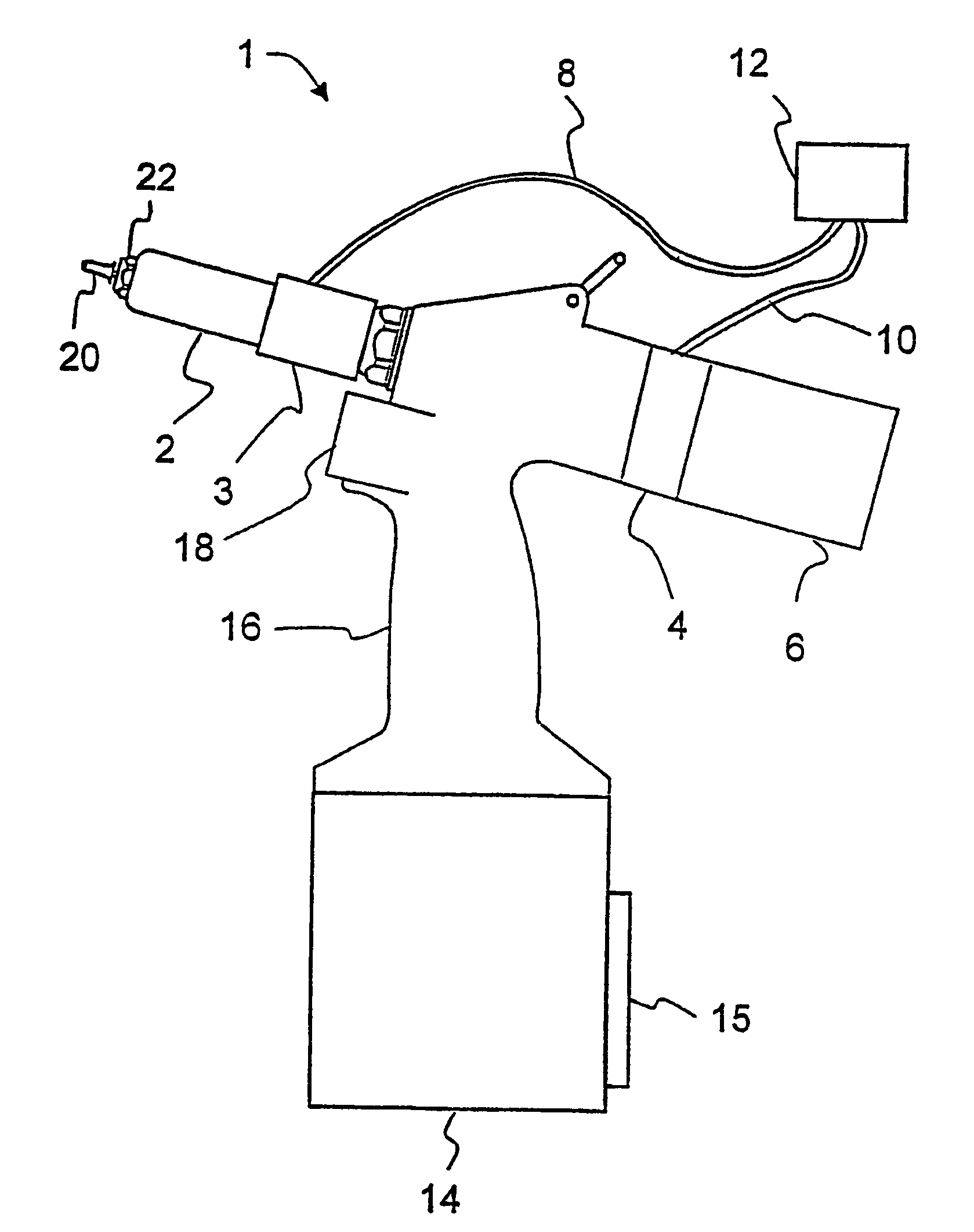
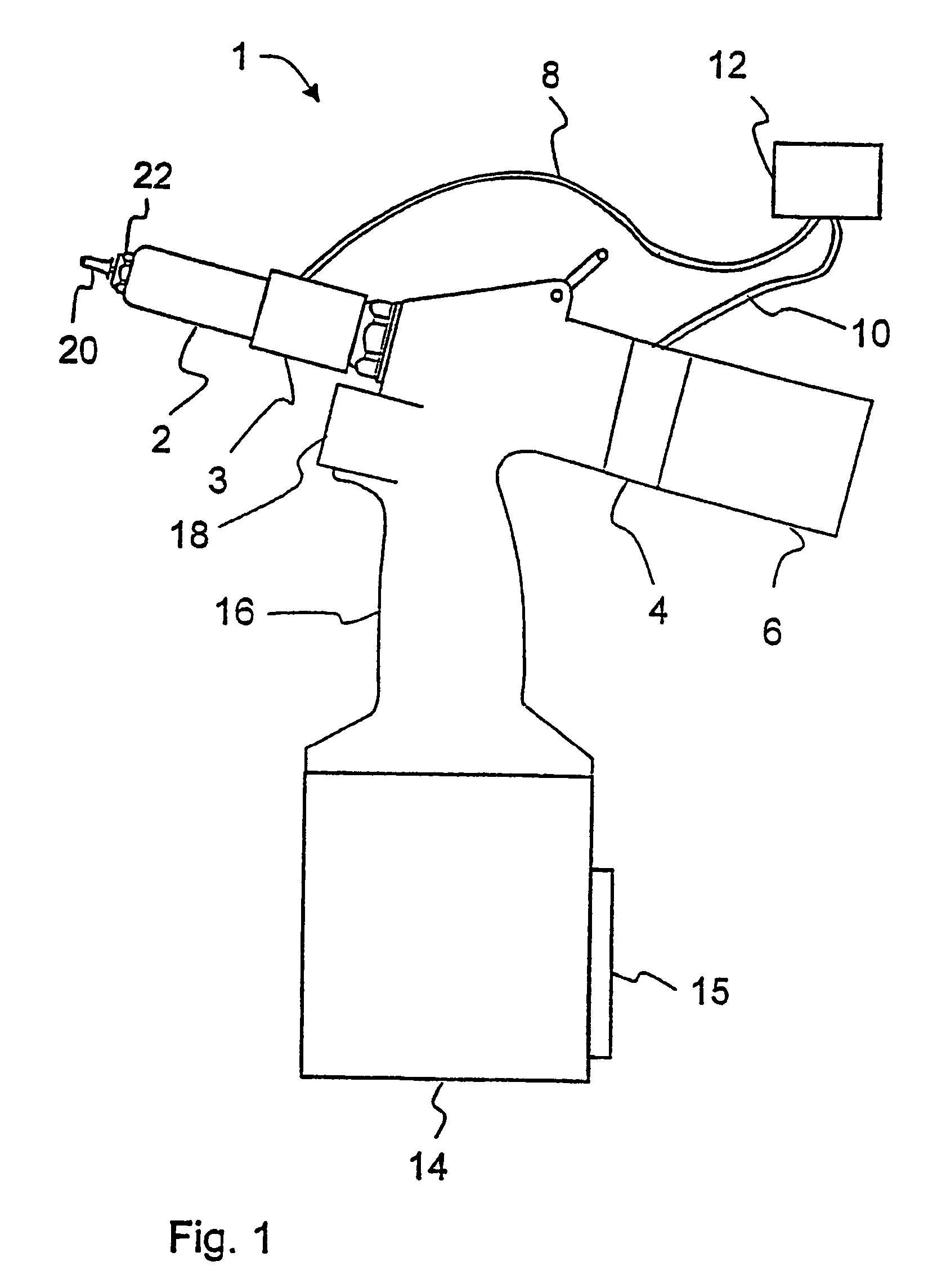
[0082]In the following description, reference will primarily be made to the rivet setting operation; this means the setting of a rivet. In this case, however, the rivet setting described comprises the setting of blind rivets, riveted nuts and, in particular, also the setting of locking ring bolts, even if this is no longer expressly mentioned. To the extent that a different head piece, mouthpiece, chuck or another holder is needed for the respective embodiment, those skilled in the art in this field can make appropriate adaptations to the current requirements.

[0083]FIG. 1 shows a schematic view of a first embodiment of the rivet setting implement according to the invention. The rivet setting implement 1 comprises a head piece 2 with adjusting nut 22 for holding a rivet 20, a body part 6 and a handle 16. Using a manually actuated triggering device 18, a pulling apparatus in the interior of the rivet setting implement is triggered, being connected to a device for gripping the shank or...


PUM

PropertyMeasurementUnit
Timeaaaaaaaaaa
Forceaaaaaaaaaa
Angleaaaaaaaaaa

Abstract

A rivet setting tool is provided to provide improved monitoring of riveted connections during rivet setting. The rivet setting tool includes a head piece for holding a rivet, a device for gripping a rivet pin, a pulling apparatus connected to the device for gripping a rivet pin, and a device for measuring the tension of the pulling apparatus. Using the setting implement according to the invention, a cause of a fault can be determined by means of a comparison between measured values and stored values.

Description

BACKGROUND OF THE INVENTION[0001]1. Field of the Invention[0002]The invention relates to a setting tool having means for monitoring setting operations.[0003]2. Description of Related Art[0004]Setting tools having means for monitoring the setting operation are known.[0005]For example, in DE 44 01 134, a method is described in which a force component is measured over the distance of the stroke and compared with a desired curve. The intention is to monitor whether the setting operation has been carried out properly.[0006]EP 0 738 551 (U.S. Pat. No. 5,666,710) discloses an apparatus for checking the setting of blind rivets. Here, the tensile force and the position of the draw shaft are measured. The energy converted is determined via an integrator and compared with a desired value.[0007]The disadvantage with these known means for monitoring the setting operation is that, although it is possible to determine with a certain probability whether the setting operation lies within a given tol...

Claims


Application Information

Patent Timeline
IPC IPC(8): B21J15/28B23P11/00B23Q17/00B21J15/04B21J15/06
CPCB21J15/043B21J15/105B21J15/28B21J15/285Y10T29/49771Y10T29/53739Y10T29/53748Y10T29/5373
Inventor SOLFRONK, ANTONIN
Owner MS GERATEBAU
Why Eureka
Try Eureka