
Projection system with a common light source sharing system

a technology of projection system and light source, applied in the direction of instruments, polarising elements, lighting and heating apparatus, etc., can solve the problems of lack of illumination uniformity, low resolution of large display, and general failure of multi-lamp projection system to achieve the effect of improving illumination uniformity

Inactive Publication Date: 2008-03-18
THOMSON LICENSING SA
View PDF8 Cites 3 Cited by
  • Summary
  • Abstract
  • Description
  • Claims
  • Application Information

AI Technical Summary

Benefits of technology

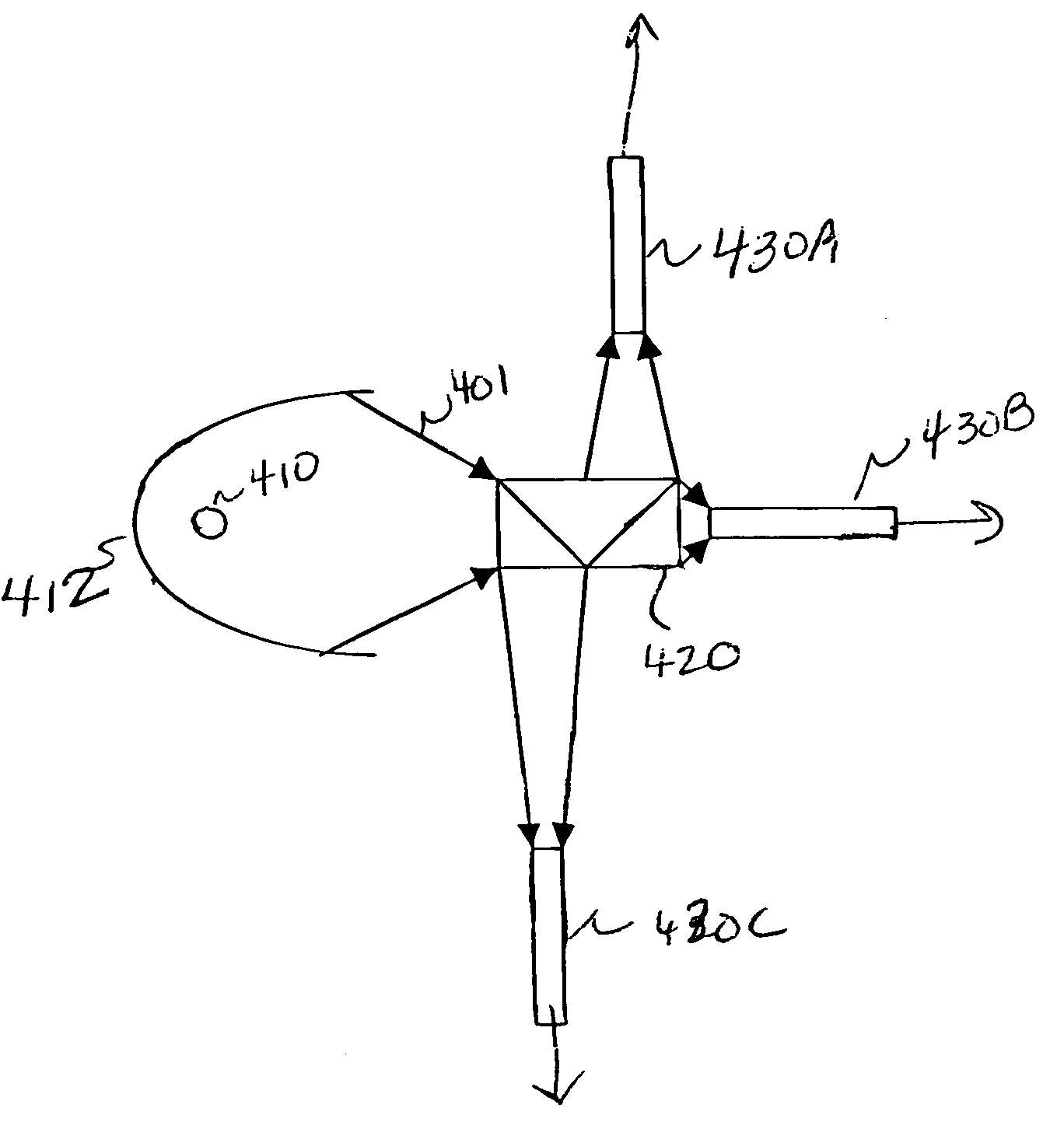
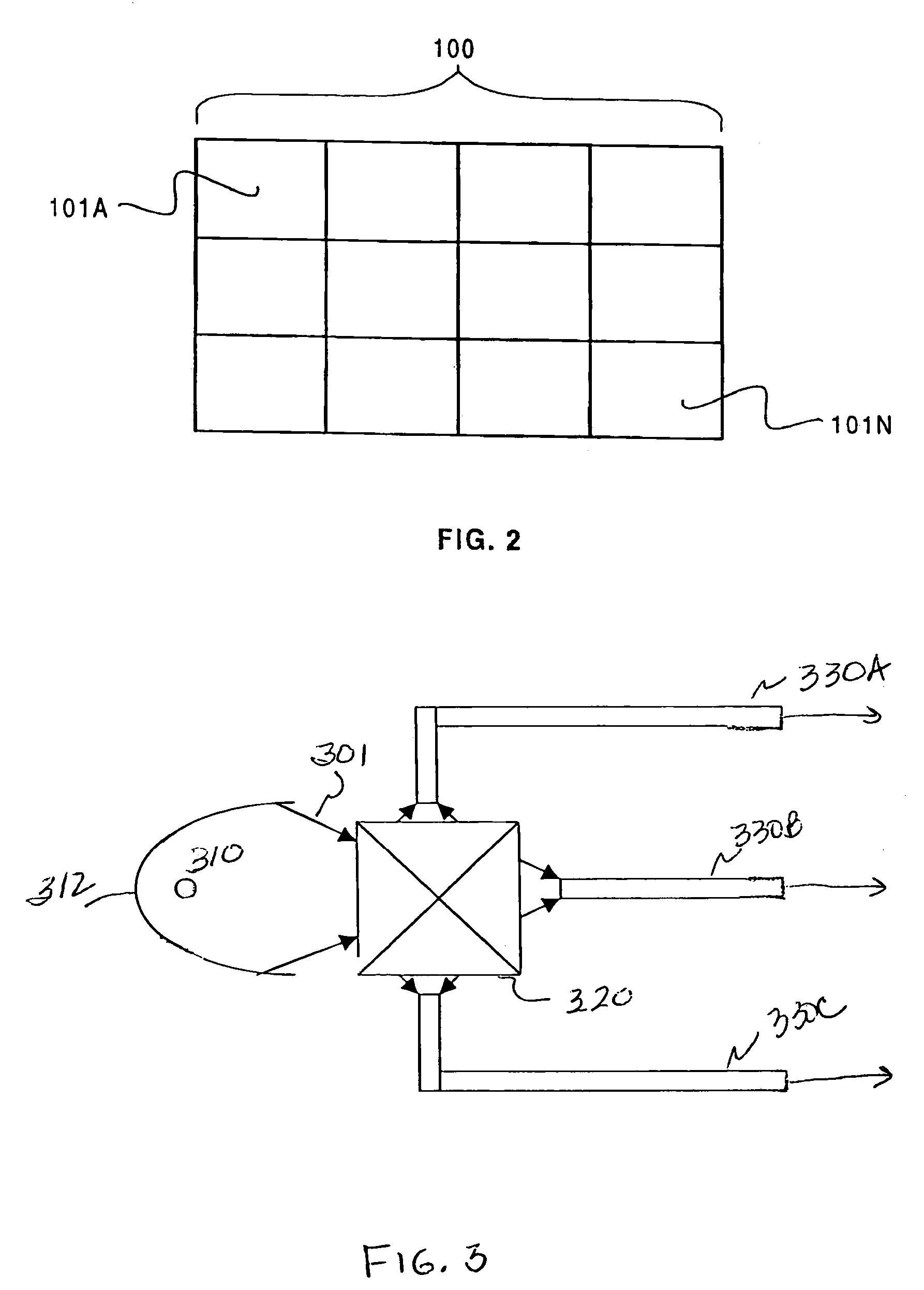
[0006]The present invention provides a projection display with a common light source sharing system for improved illumination uniformity. A common light source is coupled through a light-dividing prism to multiple integrators. Each integrator is coupled to one or more imaging devices that project image tiles to form a larger composite tiled image.

Problems solved by technology

Displaying such low resolution on a large display yields unacceptable picture quality, for example, an SVGA display projected as a 10-foot diagonal image has a minimum pixel size of approximately ⅛-inch by ⅛-inch.
Such multi-lamp projection systems have generally proved less than satisfactory, because of a lack of illumination uniformity between the tiles.
This lack of illumination uniformity is typically caused because each lamp exhibits differing brightness and color characteristics as compared to the other lamps in the system.

Method used


Image

  • Projection system with a common light source sharing system
  • Projection system with a common light source sharing system
  • Projection system with a common light source sharing system

Examples


Embodiment Construction

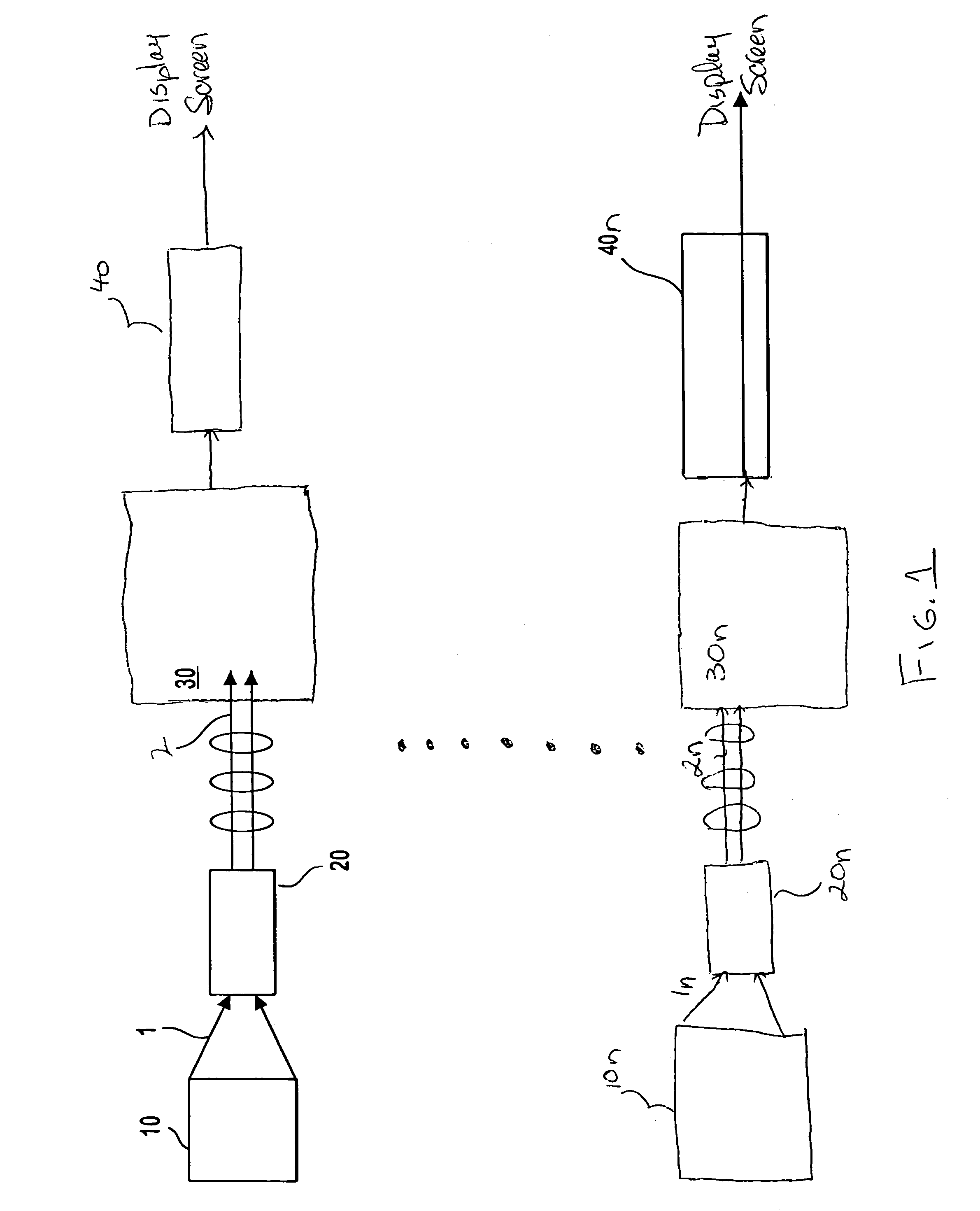
[0012]FIG. 1 shows an example of a prior art projection display apparatus that can be used for projecting each tile of a tiled display. White light 1 is generated by a lamp 10. Lamp 10 may be any lamp suitable for use in a microdisplay system. For example a short-arc mercury lamp may be used. The white light 1 enters an integrator 20, which directs a telecentric beam of white light 1 toward the projection system 30. The white light 1 is then separated into its component red, green, and blue (RGB) bands of light 2. The RGB light 2 may be separated by dichroic mirrors (not shown) and directed into separate red, green, and blue imagers within projection system 30 for modulation. The modulated RGB light 2 is then recombined by a prism assembly (not shown) and projected by a projection lens assembly 40 onto a display screen (not shown). Alternatively, the white light 1 may be separated into RGB bands of light 2 in the time domain, for example, by a color wheel (not shown), and thus direc...


PUM

PropertyMeasurementUnit
shapeaaaaaaaaaa
pixel sizeaaaaaaaaaa
widthaaaaaaaaaa

Abstract

A projection display with a common light source sharing system for improved illumination uniformity is described. The common light source is coupled through a light-dividing prism to multiple integrators. Each integrator is coupled to one or more imaging devices that project image tiles to form a larger composite tiled image.

Description

CROSS-REFERENCE TO RELATED APPLICATIONS[0001]This application claims the benefit of U.S. Provisional Patent Application Ser. No. 60 / 458,642, entitled “COMMON LIGHT SOURCE SHARING SYSTEM” and filed Mar. 28, 2003, which is herein incorporated by reference in its entirety.FIELD OF THE INVENTION[0002]The present invention is directed to projection display devices and, more particularly to light engines for projection display devices.BACKGROUND OF THE INVENTION[0003]There is a high demand among consumers for high-definition large screen displays such as, for example, liquid crystal displays (LCDs), digital light pulse (DLP) displays and Liquid Crystal on Silicon (LCOS) displays. Typical liquid crystal displays (LCDs) for consumer applications have SVGA resolution of approximately 600×800 pixels, although high-end projection displays have been introduced with up to 1920×1080 pixels. Displaying such low resolution on a large display yields unacceptable picture quality, for example, an SVGA...

Claims


Application Information

Patent Timeline
Patent Type & Authority Patents(United States)
IPC IPC(8): G03B21/28F21V7/04G02B27/12G02B27/14G02B5/30G02B6/34G02F1/1335G03B21/00
CPCG03B21/00G03B21/005
Inventor YOON, YOUNGSHIK
Owner THOMSON LICENSING SA
Learn More