Apparatus for collecting ground radar data with polarization information

a technology of ground radar and polarization information, which is applied in the direction of measuring devices, instruments, and detection using electromagnetic waves, can solve the problems of achieve the effects of less sensitive to interference, reduced interference sensitivity, and high demands on signal transfer quality

Inactive Publication Date: 2008-03-18
MALA GEOSCI FORVALTNINGS
View PDF10 Cites 35 Cited by
  • Summary
  • Abstract
  • Description
  • Claims
  • Application Information

AI Technical Summary

Benefits of technology

[0012]According to one example of the invention, there is provided a transmitter unit and sampler unit plus an A / D converter contained in the sampler unit being supported by a pair of antennas. A power source and a control unit are located in a main body and are electrically connected to the transmitter unit and sampler unit via a slip-ring arrangement. Thereby, only radar signals in digital form are transferred via the slip-ring arrangement. Since digital signals are considerably less sensitive to interference than analogue signals, the advantage is realized in that the analogue high frequency radar signals emitted from the transmitter unit are received by the sampler unit and converted to digital signals before being transferred via the slip-ring arrangement to the control unit in the main body for further processing.
[0013]This can be compared with known ground radar apparatus with rotating pairs of antennas where the other constituent parts of the ground radar used for processing radar signals, such as the power source, control unit and transmitter and sampler units are located in the main drive body of the ground radar. The disadvantage of this arrangement is obvious, since high frequency and consequently interference-sensitive signals via slip-ring arrangements or similar means of signal transfer must be transferred from the antennas to the sampling unit located in the main body. Not least, such an arrangement puts high demands on the signal transfer quality of the slip-ring arrangement or similar means of transferring signals between the antenna and the sampler. Because the sampler unit according to this invention is located on the rotating receiver antenna, the high frequency radar signals can be converted into digital signals before they are sent for further processing to the control computer in the main body via the slip-ring arrangement. This gives a number of advantages, amongst other things sensitivity to interference is reduced and it is possible to use cheaper and simpler slip-ring arrangements.
[0014]A slip-ring arrangement links the antennas and a power source located in the main body. The slip-ring arrangement offers a continuous electrical contact between the power source and the pair of antennas, whereby only digital control signals and DC voltages are transferred through it. Consequently only simple signals pass through the slip-ring arrangement and the number of signals passing through it is minimised.
[0015]Analogue HF equipment connected to the transmitter and receiver antenna can well be located in the housing. The extra weight this entails is practically negligible in comparison with the weight of the screens and RF damper used to make up the antenna housing.

Problems solved by technology

The disadvantage of this arrangement is obvious, since high frequency and consequently interference-sensitive signals via slip-ring arrangements or similar means of signal transfer must be transferred from the antennas to the sampling unit located in the main body.
Not least, such an arrangement puts high demands on the signal transfer quality of the slip-ring arrangement or similar means of transferring signals between the antenna and the sampler.

Method used


Image

  • Apparatus for collecting ground radar data with polarization information
  • Apparatus for collecting ground radar data with polarization information

Examples


Embodiment Construction

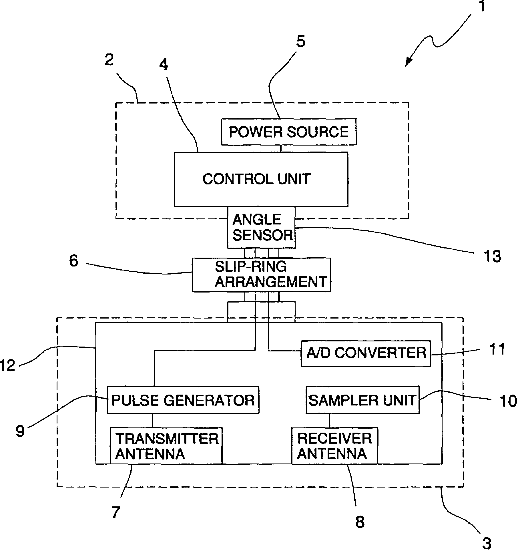
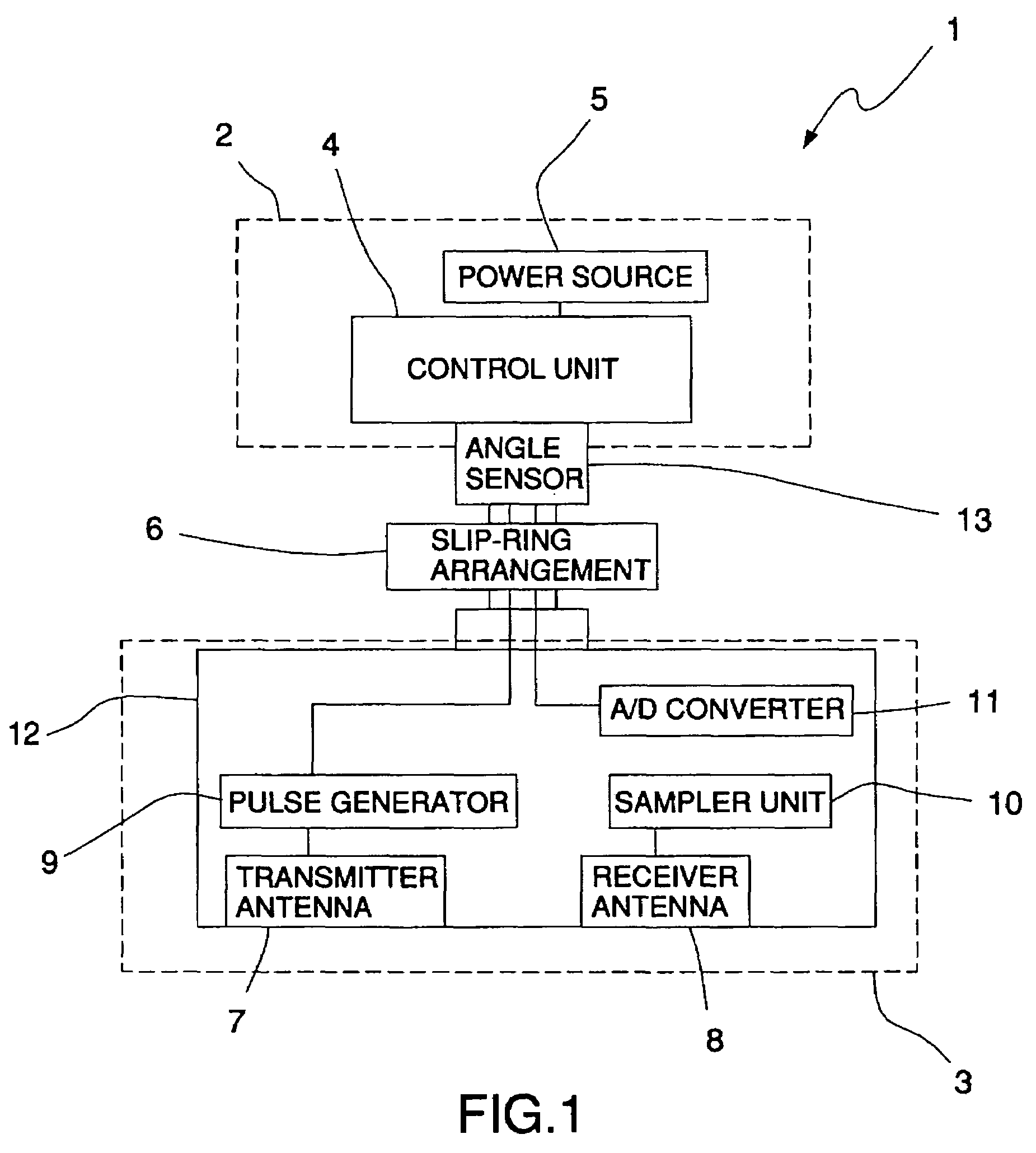
[0021]The apparatus generally referred to with the number 1 comprises a main body 2 and a part 3 that is pivot mounted to the main body 2. The main body 2 of the apparatus 1 comprises a control unit 4 and a power source 5. A slip-ring arrangement 6 and an angle sensor 13 are located between the main body 2 and the part 3. The part 3 comprises a transmitter 7 and a receiver 8. The transmitter antenna 7 and the receiver antenna 8 are plane parallel and contained in a casing 12. The transmitter antenna 7 has an associated pulse generator 9 and the receiver antenna 8 has a sampler 10 and an analogue to digital A / D converter 11. Both the transmitter unit (9) and the sampler unit (10) are supported by the rotating pair of antennas (7, 8) like the A / D converter (11) included in the sampler unit. This design offers the advantage that the analogue high frequency radar signals sent from the transmitter unit can be received by the sampler unit and converted to digital signals before they are c...


PUM


Abstract

The present invention concerns an apparatus for collecting ground radar data with polarization information comprising a main body exhibiting structure for moving the apparatus along the ground, a part that rotates in relation to the main body supporting a pair of antennas of transmitter and receiver type, a power source with connected control unit for controlling and governing the ground radar, a transmitter unit electrically connected to one of the pair of antennas for generating and transmitting radar pulses and a sampler unit electrically connected to the other antenna for receiving the reflected radar pulses. To improve signal quality and reduce sensitivity to interference, the rotating pair of antennas support the transmitter unit, sampler unit and A/D converter contained in the sampler unit, the power source and the control unit are located in the main body and are electrically connected to the transmitter unit and sampler unit via a slip-ring arrangement, in which the radar signals are conveyed digitally via the slip ring arrangement.

Description

[0001]This application is the U.S. national phase of international application PCT / SE2003 / 001914, filed 9 Dec. 2003, which designated the U.S. and claims priority of SE 0203695-2, filed 13 Dec. 2002, the entire contents of each of which are hereby incorporated by reference.BACKGROUND OF THE INVENTION[0002]The present invention concerns an apparatus for collecting ground radar data with polarization information.[0003]In the following, polarization data is taken to mean including information on the electrical field direction of the radar wave.[0004]Ground penetrating radar (GPR), also called ultra wideband radar, is a kind of time-dependent radar system characterized by its high bandwidth. Commercial GPR system have a typical bandwidth in excess of 1.[0005]To study the characteristics of a land area or more generally a sample medium a radar system is used in which one antenna transmits electromagnetic signals and another antenna registers the signals that are reflected from the sample...

Claims


Application Information

Patent Timeline
Patent Type & Authority Patents(United States)
IPC IPC(8): G01S13/88G01V3/12G01S13/00G01V3/15
CPCG01S13/88G01V3/15G01S13/885
Inventor FRIBORG, JOHANJOHANSSON, BERNTLEIJON, TOMMY
Owner MALA GEOSCI FORVALTNINGS
Why Eureka
Try Eureka